


An Electric Brake-servo Device
Page 72
If you've noticed an error in this article please click here to report it so we can fix it.
A Resurnd of Recently Published Patent Specifications
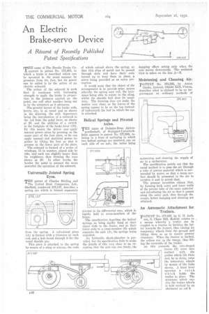
ririflE name of The Bendix Brake Co. 1 appears in patent No. 378,405, in Which a brake is described which can be operated in the usual manner by pressure from the foot, but its power can be added to by the action of an electric solenoid.
The action of the solenoid iS such that it continues with increasing strength to apply the brake in proportion to the pressure exerted on the pedal, one coil after another being out in by the armature as it advances.
The general layout of the brake rods, levers, etc., is as usual and as shown in the drawing, the only departures being the introduction of a solenoid in the rod from the pedal lever, as shown at 20, and the addition of a switch in the footplate of the brake lever (16). By this means the driver cam apply manual power alone by pressing on the upper part of the foot plate, or he can apply manual and electrical power together by tilting his foot so that it presses on the lower part of the plate.
The solenoid is formed of a series of windings 13 in number, placed side by side, and each one slightly larger than its neighbour, thus forming the cone shown at 20. In other words, the harder the pedal is pressed the more powerful the operation of the solenoid.
Universally Jointed Spring Eyes.
TEE patent of Charles Stirling and The United Steel Companies, Ltd., Sheffield, numbered 378,137, describes a spring eye which is formed separately from the spring. A cylindrical piece (A) is formed with a trunnion at each end, and a hole bored through it for the usual shackle pin.
This piece is attached to the sp.ring by means of a sling or stirrup, the ends of which extend above the spring, so that thin slips of metal can be passed through slots and have their ends turned up to keep them in place, a screw being provided as an extra precaution.
It would seem that the object of the arrangement is to provide some means whereby the spring may roll, the trunnions being able to rotate in the sling, whilst the shackle bolt does its usual duty, The drawing does not make the matter very clear, as the leaves of the spring appear to be on the top instead of underneath the leaf to which the eye is attached.
Helical Springs and Pivoted Axles.
THE name of Daimler-Benz Aktien gesellschaft, of Stuttgart-Unterturkbeim appears in patent No. 377,900, relatiug to a form of springing in which two helical springs are mounted, one on each side of an axle, the latter being pivoted to its differential case, which is rigidly held to cross-members of the frame.
The specification describes the helical springs as being rigidly fixed at their upper ends to the frame, and at their lower ends to a cross-member (6) which supports the axle (3), the springs being unguided. .
An hydraulic shock-absorber is provided, but the specification fails to make the details of this very clear to us, excepting that the axle can rise freely, the damping effect acting only when the axle moves downwards. The sectional view is taken on the line A—B.
Moistening !and Cleaning Air.
PATENT No. 378,263, .by Anton Gazda, Arsenal, Objekt XIX,Vienna, describes what is claimed to be an improvement on ordinary methods of moistening and cleaning the supply of air to a carburetter.
The specification points out that the usual method is to pass the air through a tube of porous material which is surrounded by water, so that a damp surface should be presented to the air to moisten it and to arrest dust. • The present invention claims that, by forming both outer and inner walls of the porous tube of the same material and introducing the air so that it passes along the outer part, then through the centre, better damping and cleaning are attained.
An Automatic Attachment for Trailers.
p ATENT No. 377,687, by G. H. Jack
son, 6, Chase Hill, Enfield, relates to a means whereby a trailer can be coupled to a tractor by backing the latter towards the former, thus raising its temporary wheels from the ground and tilting them so as to ensure greater Clearance. When the tractor is backed, the rollers run up the ramps, thus lifting the turntable of the trailer. As this proceeds the cam-shaped levers (9) come into contact with the guides which lift them and, by so doing, raise the temporary wheels by means of the links shown. A band lever operates a catch which holds the trailer in place. The structure which carries the trailer wheels is held vertical by an abutment on rod 9.