


• Two New
Page 70
If you've noticed an error in this article please click here to report it so we can fix it.
SALERNI INVENTIONS
A Resume of Recently Published Patent Specifications
WE haw for many years in this journal predicted the coming of some means for disconnecting the drive from the gearbox to the rear axle by means of a special kind of clutch, during the operation of changing gears, as a possible solution of the problem of obtaining an easy gear change.
If the number of patents that has recently been granted for devices of the kind may be, taken as all indication of a trend in this direction, we may expect to become popular the fitting of a clutch behind the gearbox.
Two patents bearing the name of Piero Mariano Salerni, numbered 333,222 and 333,234 respectively, appear this week. Patent No. 333,234 relates to a coupling or clutch in a form which has already been described, but as many of our readers may not be familiar with the details of the device, we reproduce some of the drawings from the specification, together with a brief description.
A represents the driving shaft and B the driven. B1 is a dog member which is keyed to its shaft (B), whilst Al is a mating member, but can slide on splines for engagement and disengagement. C is a baulk ring, which is described as a synchronizer " ; we do not, however, agree with this term, as a baulk ring merely baulks, and serves to Prevent engagement until synchronization takes places, it does not cause synchronization. As shown in Fig. 1, the clutch is disengaged. Fig. 2 shows the clutch engaged.
The two smaller viws show the device in section and indicate how it operates.
Specification No 333,2= refers to a coupling in which the same means are employed to Prevent engagement until synchronization occurs, but it also describes a means whereby synchronization can be brought about by the introduction Of a multi-plate friction clutch, which, it is claimed, will produce sufficient friction to cause an engine to start.
There are undeniable indications that the Whole problem • and principle of clutch engagethent with synchronization are likely to come into prominence in the near future, and several purposes can be served by solution of the difficulties.
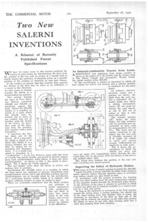
• An Internal-combustion Tractor from Leeds.
A SOMEWHAT new departure from steam practice is shown in the patent of C. II. Fowler and H. Cooper, both of The Steam Plough and• Locomotive Works, Leeds, the patent number being 333,347.
, In this specification a tractor is described in which all four wheels are driven and steered, and a tubular member is employed for the main
franAle. ordinary unit-construction engine and a gearbox are shown ; the . shaft from the unit carries a gearwheel (3) of double width into which a sliding intermediate pinion (2) can mesh for driving the road wheels, or can be slid out of action so that it only drives the pulley.
The tubular member (K) forms the Main frame, but side members (B) are provided and are connected at their ends by cross-members (C and CI). The front axle is rigidly connected to the frame, but the rear axle is pivotally mounted at E to enable the vehicle to travel over uneven ground. Differentials, are employed in both axles.
Fig. 3 shows the arrangement by which the
wheels can drive and steer, the shaft (Fl) transmitting power through the universal joint (G) to the pinion (Ga) and thence to the internally toothed wheel (10).
The dotted lines indicate the position of the rear axle when travelling over uneven ground.
Improving the Safety of Hydraulic Brakes.
THE name of Louis Coatalen appears in patent No. 333,365, which describes a means whereby the fluid under pressure which operates brakes through separate pipes is prevented from feline should one pipe break or leak. In accordance with the present invention the drawing shows two pipes leading from the main compression cylinder to two separate brakes through the horizontal pipes shown. At the junction of the pipes a cylinder is provided in which a piston can slide, but is retained normally in a central position by a ball and spring.
So long as the resistance to movement of the fluid remains normal the piston keeps a central position, but should one of the pipes leading from this chamber leak or break, the resistance to movement of the fluid on that side of the piston will be reduced, the pressure on the other side causing the piston to .move to one • side, thus turning itself into a valve and stopping fluid from escaping.