


SOME USEFUL WORKSHOP TOOLS.
Page 26
Page 27
If you've noticed an error in this article please click here to report it so we can fix it.
Two of Our Readers Impart Interesting Ideas for the Benefit of Others.
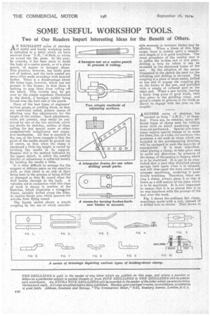
AN EXCELLENT series of sketches of useful and handy workshop tools is embodied in a letter which we have received from F.1-1.," of Bath, to whom we award the 15s. prize. In the past, he remarks, it has been usual to make the body of a centre punch, or of a plain punch, of square or hexagon shape. This practice, however, has lately gone out of fashion, and the tools named are more often made nowadays with knurled bodies. There is a disadvantage about the latter type, however, which was not present in the former, in that there is nothing to stop them from rolling -off the bench. This trouble may be got over by the simple expedient illustrated in the sketch, a hexagon washer being forced over the butt end of the punch. Many of the best types of engineers' surface gauge,.or scribing block, as they are sometimes called, possess means Of effecting very fine adjustments for the height of the scriber. Such adjustment, when not present., may easily be contrived by one of the two methods which are shown by sketches, neither of them calling for any special screw or other comparatively complicated and expensive mechanism. All that is required in the case of the lower example is that the point of the needle should be ground out of centre, so that when the clamp is slackened a little the height is varied by twisting the needle in its support.
Simpler is the method indicated by the upper sketch, in which the needful facility of adlestment is achieved merely by bending the needle a little.
It is often difficult to arrange for the support of delicate parts on the sensitive drill, so that there is no risk of their being bent in the process of being drilled or damaged as they fly round when the
drill breaks through at the back. A valuable aid in connection with this class of work is shown in another of the ketches, which illustrates a triangular frame, suitably drilled along the sides, to receive thrust pins 'which prevent, the articles from flying round.
The fourth sketch shows a simple coupling by the use of which consider
able economy in hacksaw blades may be effected. When a blade of this type snaps, there is usually quite a respectable length of it in good condition. The usual procedure of the careful man is to soften the broken end of this piece, drilling a bole by which it can be mounted in the shortened frame of the saw. By the adoption of the means illustrated in the sketch the need for the softening and drilling is obviated. The coupling is a piece of sheet metal, drilled at one end to engage the coupling pin on the frame of the saw, and provided -with a couple of collared pins at the other end. When a saw breaks leaving a fairly long piece of good blade, take that piece to the grinding wheel, and grind a couple of grooves in the blade as shown to engage with the pins on the coupler.
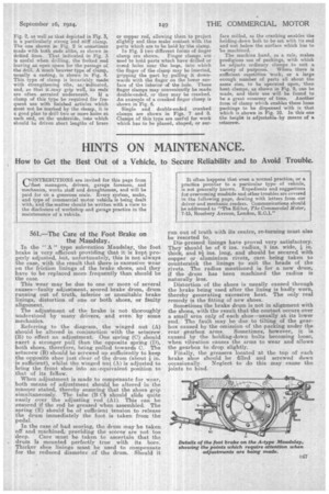
ANOTHER series of sketches has reached us from " .1.1-I.N.," of Stamford. There are, he remarks, many different types of clamp used for holding down work on which machining opera tions are performed. Special jobs sometimes require special clamps to be made for them, but, as a rule, the mechanic who possesses a set such as those which are included in the accompanying sketches, will be equipped to meet the majority of emergencies. It is most important, when placing a clamp, to take great care to avoid any distortion, by pressure of the clamp, of the casting or forging which is to be machined. It is apt to be overlooked that a part thus distorted always springs back again when it is released, and will thus upset the most careful and accurate machining, rendering it practically worthless, Therefore, when setting a clamp, always place it so that it bears on a stiff section of the piece which is to be machined. It is also important to ensure that it is so placed that it in no way interferes with the passage of the tool over the work.
Fig. 1 shows the ordinary flat clamp, sometimes madeswith a slot, instead of a drilled hole as shown. That shown in Fig. 2, as well as that depicted in Fig. 3, is a particularly strong and stiff clamp. The one shown in Fig. 2 is sometimes made with both ends alike, as shown in dotted lines. That. indicated. in Fig. 3 is useful when drilling, the forked end leaving an open space for the passage of. the drill. A much heavier type of clamp, usually a. casting, is shown in Fig. 4. This type of clamp is invariably made with strengthening ribs, as? indicated, and, so that it may grip well, its ends
are often serrated underneath. 1£ clamp of this type be required for frequent use with finished articles which must not be. marked by the clamp, it is a good plan to drill two or more holes at each end, on the underside, into which should be driven short lengths of brass
or copper rod, allowing them to project slightly and.thus make contact with the parts which are to be held by the clamp. In Fig. 5 two different forms of finger damp are shown. Finger clamps are used to hold parts which have drilled or coved holes near the base, into which the finger of the clamp may be inserted, gripping the part by pulling it downwards with the finger on the. lower surface of the interior of the hole. These finger clamps may conveniently be made double-ended, or they may be cranked. An example of a cranked Ani.);er clamp is shown in Fig. 6. Single and double-ended cranked. clamps are shown in Figs. 7 and 8. Clamps of this type are useful for work which has to be planed, shaped, or sur
face milled, as the cranking enables the holding-down bolt to be set, with its end and nut below the surface which has to be machined.
The machine hand, as a rule, makes prodigious use of packings, with which he adjusts ordinary clamps to suit a
variety of purposes. Where there is sufficient repetition work, or a large enough number of parts all about the same size, to be operated upon, then bent clamps, as shown in Fig. 9, can be made, and their use will be found to he a great economy of time. Another form of clamp which enables these loose packings to be dispensed with is that which is shown in Fig. 10. in this one the height is adjustable-by means of a setscrew.