


Patents Completed.
Page 20
If you've noticed an error in this article please click here to report it so we can fix it.
Complete specifications of the following patents will be sent to any address in the United Kingdom upon receipt of eightpence per copy at the Sale Branch, Patent Office, Holborn, W.C.
CLUTCH.—Wolseley Tool and Motet Car Co., Ltd., and Others.—No. 17,807, dated 25th August, 1908,—This invention relates to friction clutches of the floating-disc type and it has for its object so to construct the clutch that the floating rings and the compression spring may be removed in one unit without disturbing their relative positions. The driving member of the clutch is in the form of a boxlike casing and contains the spring which normally forces the discs into engagement. This casing is secured by means of bolts to a cup-shaped member which partly surrounds the casing and is itself secured to the driving shaft. In order to remove the dutch it is only necessary to loosen these bolts and to disconnect the driven member, when it may be removed as one unit. The guide bars for the driving discs are provided with diametrically-opposite flat faces which engage grooves provided in the
discs, and, in order that the faces of the guide bars shall always be square with the slots in the discs, the bars are mounted in bearings in the casing.
MEANS FOR PROPELLING MOTOR VEHICLES.—Barford and Perkins.— No. 20,118, dated 25th September, 1908. —This invention relates to a device for propelling a motor-driven vehicle, when the road wheels are unable to obtain a grip on the road, owing to the latter's slippery condition. On the driving a.xle, an eccentric is mounted, the strap of which has, secured to it by suitable bolts, a rod or a leg which terminates in a shoe. When the driving wheels of the vehicle are unable to obtain sufficient grip on the road, the eccentric rods, which are normally held out of contact with the road by means of a chain and hook secured t the chassis, are lowered so that they may make contact with the road surface. It will be seen that, as the axle rotates, the shoe of the eccentric rod will be forced against the surface of the road and the vehicle urged forward.
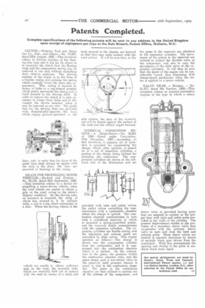
INTERNAL COMBUSTION ENGINE.—A. Sainte-Benve.—No. 25,661 of 1908.—Dated under Convention, 17th December, 1907.—According to this invention, a separate set of cylinders is provided for compressing the charge, which, after ignition, is passed on to a set of expansion cylinders, a portion of the charge being utilized for actuating the compressor. The compression cylinders are shown at the lefthand side of the illustration and are
provided with inlet and outlet valves, the outlet valves controlling the communication with a combustion chamber where the charge is ignited. The combustion chamber communicates in turn with a cylindrical reservoir in which is mounted a wring-controlled piston, and the reservoir finally communicates with the expansion cylinders. The expansion cylinders are double acting, and the admission and exhaust gases are controlled by slide valves. This engine operates as follows :—The charge is drawn into the compression cylinder from the carburetter, and it is compressed into the combustion chamber where it is ignited. On the combustion of the gases, the pressure within the combustion chamber rises, and the gases escape past a non-return valve to the reservoir until pressure therein is equal to that in the combustion chamber. The gases in the combustion chamber are then utilized to operate one of the pistons of the compressor, and the gases in the reservoir are admitted to the expansion cylinders. The movements of the piston in the reservoir are utilized to control the throttle valve to the compressor, and also to vary the movements of the slide valve of the ex. pansion cylinders. It will thus be seen that the speed of the engine can be considerably varied, thus dispensing with change-speed mechanism when the latter is applied to a motor vehicle.
VALVE GEAR. — Kitchen. — No. 21,317, dated 9th October, 1908.—This invention relates to internal-combustion engines of the type in which a rotary sleeve valve is provided having ports that are adapted to register at the proper time with inlet and outlet ports provided in the walls of the cylinder. The present improvement reSides in the provision of a secondary sleeve valve that co-operates with the primary sleeve valve to open and close the inlet and exhaust ports. These sleeve valves are rotated in opposite directions by means of suitable worm gear driven from the crankshaft. With this arrangement the opening and closing of the ports is rendered much more rapid.