


Induction-pipe Design
Page 62
If you've noticed an error in this article please click here to report it so we can fix it.
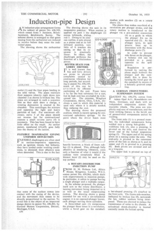
AN induction-pipe arrangement forms the subject of patent No. 696,549, which comes from .1 Jameson, Brockhamhurst, Betchworth, Surrey. The scheme shown is arranged so that gases issuing from the carburetter are induced to revolve before they enter the individual pipes.
The drawing shows the carburetter outlet (I) and the four pipes leading o the inlet valves. The pipes maintain their separate identity right down into chamber 2 as shown in broken line. The pipes are arranged in such a sequence that as they each draw a charge, a rotating depression is created in the chamber. This centrifuges the mixture and separates the light and heavy particles of fuel. For maximum efficiency, curve 3 of the pipes should not reverse, but for constructional reasons a small reverse curve (4) is necessary. This has been found to have little effect on the resplt. An earlier patent, numbered 631,659, goes fully into the theory of the action.
FLEXIBLE DIAPHRAGM GIVING UNIFORM DEFLECTION
FLEXIBLE diaphragms are often used in suction-responsive apparatus, such as ignition timers, but hitherto, they have tended under working conditions, to diminish their effective area when distended. This is due to the fact
that some of the surface comes into contact with the casing of the device, and the movement then ceases to be directly proportional to the suction. To avoid this is the object of an improved design shown in patent No. 696,402, by General Motors Corporation, Detroit, Michigan, U.S.A.
A36 The drawing shows the unit in its inoperative position. When suction is applied via port 1 the diaphragm (2) moves leftwards, sliding .
rod 3. Owing to its sinuous outline, it acts almost as a piston and at its full leftward position, very little of it touches the casing, so that its response is practically linear. In effect, the diaphragm performs the function of a frictionless piston.
• BETTER SEATS FOR LORRY DRIVERS IT is well known that bus and lorry drivers are prone to physical complaints caused by continuous vibration for long periods, but according to patent No. 696,349, much of this can be avoided by efficient cushioning of the seat. Foam latex is by far the best substance for a seat, but its high cost has precluded its widespread use. The patentee, Wingfoot Corporation, Akron, Ohio, U.S.A., discloses a seat in which this material is used only where it is strictly needed, thus reducing the cost.
The drawing shows the proposed cushion, which is mainly sprung by conventional upholstery springs. At the point where the driver bears most heavily however,, a block of foam rubber (1) is placed. This, although fully effective in insulating vibration, costs only a fraction of what it would if the cushion were completely filled. A thinner layer (2) may be used on the top surface.
A ROTARY-DISTRIBUTOR INJECTION PUMP UROM H. M. Hobson Ltd., Africa House, Kingsway, London, W.C.2, comes patent No, 694,966, which deals with improvements in injection pumps. In particular, it refers to pumps having a single plunger and a multiple output.
In the scheme proposed, the plunger itself acts as the rotary distributor, a turning movement being imparted to it as well as the usual reciprocating motion. The drawing shows a pump intended for use with a six-cylindered engine; it is an opposed-plunger layout, each plunger serving three cylinders.
A three-lobed cam (1) reciprocates the plunger three times in a revolution, whilst a bevel gear on the camshaft meshes with another (2) on a rotary sleeve (3).
The sleeve thus makes one-third of a revolution per plunger stroke, and the rotary motion is transferred to the plunger via a pin-and-slot connection (4) to a guide in which the plunger fits on its squared end (5). As the plunger turns, its spill groove lines up in succession with the three discharge ports (7).
In order to prevent side thrust on the plunger, a balance slot can be provided at a point opposite to the spill groove.
Regulation is performed by varYing the phase angle between the plunger and the camshaft; this is done by turning the bevel gear on the camshaft by means of a helically grooved coupling.
A GERMAN FRONT-WHEEL SUSPENSION SYSTEM
PATENT No. 696,276, comes from Adam Opel A.G., Russelsheim am Main, Germany, and deals with an independent suspension system for steerable wheels. The aims are simplicity and ease of manufacture, and the most striking feature is the lavish use of pressed-steel components united by welding.
The front axle (1) is a pressed member, the individual components being welded into a strong box-girder. A wishbone link (2), also a pressing, is pivoted on the axle, and receives the lower end of the helical suspension spring (3). The upper end of the spring abuts on a seating under the axle, The stub-axle is pivoted in the outermost point of the link as shown at 4, and its upper end (5) is pivoted in a pressing (6). Both pivots are co-axial and act as a king-pin.
The upper link is pivoted on top of a hat-shaped pressing (7) attached to the front axle. The frame side-member, indicated by broken line (8), surrounds the hat, rubber washers being interposed. These are claimed to reduce the transmission of noise to the chassis, A cylindrical shock-absorber is located centrally inside the helical spring.