


AN EASILY DEMOUNTABLE RADIATOR.
Page 70
If you've noticed an error in this article please click here to report it so we can fix it.
A Resume of Recently Published Patent Specifications.
ASIMPLE and apparently efficient design of a radiator for commercial motors is shown in the specification of A. W. H. Bull, No. 258,084. Instead of the multiplicity of small bolts that are usually employed to hold the upper and lower tanks to the plates that carry the tubes, long bolls are used to hold the three elements together. A channel is provided to receive a rubber ring that passes all round the joint to make a watertight seal,
From the description it would seem that the tubes have to bear the whole of the compression necessary to prevent leakage, whic h, considering the very large area of rubber to be compressed, must be considerable. Such tubes are usually of the thinnest gauge, and therefore will not stand much compression, , but, owing to their great number, it is probable thet they may withstand the pressure. The large tubes that contain the bolts will materially help to hear the compression.
We feel sure that radiators made according to this plan would, if successful, be welcomed by those who have to keep fleets of vehicles in repair, as in a few minutes the whole thing can be taken to pieces.
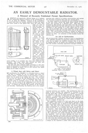
A Wheel that will Drive and Steer.
IN specification No. 258,685 C. A. Freeland shows a wheel hub that is suitable for use on vehicles that drive the steering wheels. Another feature of his invention is that a brake can be made to act within the hub. The sectional view on the left shows the full floating axle in the centre, to which is attached a pair of trunnions that form the universal joint to transmit power to the wlaeel hub for driving. In the centre of the right-hand view will be seen the two grooves in which the blocks of the universal joint work. A. central pin controls the position of the floating axle laterally. Surrounding the floating axle is Ike weight carrying axle, which is, of course, non-revolving, and carries the two large trunnions that form the steering pivot.
On these trunnions is mounted the non-revolving member of the hub which carries the brake shoes, shown in both views, and operated by a Bowden wire, Pall races are. mounted on this member, and upon them runs the revolving member which forms the hub, and also acts as a brake drum.. Attached to this member is a plate which acts as a hub cap, and is provided with a boss extending inward, which, , being formed to take the universal joint, acts as the driving Plate. The non-revolving member is formed in halves to . enable it to be located in the trunnions, and may be clamped together by bolts. An extension of this member fortes the
steering arm. •
An Aid to Carburation
JUAN MANUEL VIDAL, of Buenos Aires, in specification •
'No. 258,016, describes an apparatus which, he claims, provides for an •engine an explosive mixture that is as near • as possible ideal for all speeds and conditions of running, sothat the troubles commonly experienced through working on incorrect mixtures are avoided. The specification does not make it clear whether the apparatus is intended to use heavier fuels than ordinary petrol, or whether it is merely an adjunct TO the use of petrol through an ordinary carburetter. A carburetter is described as being fitted to anordinary manifold. Two pipes lead from the apparatus to the manifold, one apparently as a main source of supply andone as a supply of extra air.
The apparatus consists of a fuel tank fixed on the dash, from which a pipe leads to a saddle-shaped vaporizer which hogs the exhaust pipe, as shown in the small view on the right. The fuel enters the vaporizer and passes through what is described as a Primus burner, but no mention is made of burning, so we presume this device merely acts as an atomizer. After being acted upon by the heat derived from the proximity of the exhaust pipe, the spray becomes a vapour that leaves the vaporizer, partly through the filter to the carburetter and partly through the pipe leading to the manifold. Cold air enters through the valve on the left of the vaporizer, and extra cold air is allowed to enter the manifold through the suction-actuated valves shown where the pipe from the vaporizer joins the manifold. To provide for an accumulation of explosive mixture that may become a danger in the vaporizer a relief valve is fitted as shown.