


THE TORQUE CONVERTER IN OPERATION.
Page 61
Page 62
Page 63
If you've noticed an error in this article please click here to report it so we can fix it.
THEinvention of Mr. Constantinesco which during the last year or two has attracted so much interest in engineering circles has, after a long period of experimental and research work, taken a concrete form and is now being demonstrated in the shape of a private tar ready to be offered to the public. The principle employed is one that has never been used in a practical form before, so one can easily imagine that Mr. Constantinesco has had much work to do, as the path be was following was one in which little or no research_ work had been done previously.
Although this device has been described in the technical and general Press many times, most of the descriptions are more likely to mislead than to make the very simple principle understandable.
,To begin with, it is, perhaps, best to state plainly what the device accomplishes, and after that we will do our best to make all the workings of the mechanism clear.
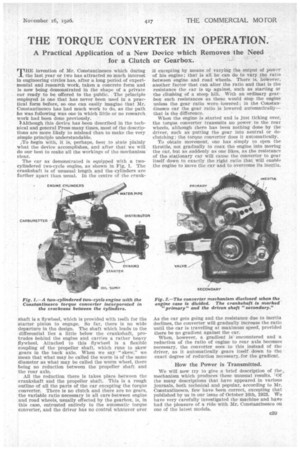
The ear as demonstrated is equipped with a twocylindered two-cycle engine, as shown in Fig. 1. The crankshaft is of unusual length and the cylinders are farther apart than usual. In the centre of the crank shaft is a flywheel, which is provided with teeth for the starter pinion to engage. So far, there is no wide departure in the design. The shaft which leads to the differential lies a little below the crankshaft, protrudes behind the engine and carries a rather heavy flywheel. Attached to this flywheel is a flexible coupling of the propeller shaft, which runs to skew gears in the back axle. When we say • " skew," we mean that what may be called the worm is of the same diameter as what may be called the worm wheel, there being no reduction between the propeller shaft and the rear axle.
All the reduction there is takes place between the crankshaft and the propeller shaft. This is a rough outline of all the parts of the car excepting the torque converter. There is no clutch and there are no gears, the variable ratio necessary in all cars between engine and road wheels, usually effected by the gearbox, is, in this case, entrusted entirely to the automatic torque converter, and the driver has no control whatever over
it excepting by means of varying the output of power of his engine; that is all he can do to vary the ratio between engine and road wheels. There is, however, another factor that can alter the ratio and that is the resistance the car is up against, such as starting or the climbing of a steep hill. With an ordinary gearbox such resistances as these would stop the engine unless the gear ratio were., lowered; in the Constantinesco car the gear ratio is lowered automatically— that is the difference.
When the engine is started and is just ticking over, the torque converter transmits no power to the rear wheels, although there has been nothing done by the driver, such as putting the gear into neutral or declutching; the torque converter does it automatically.
To obtain movement, one has simply to open the throttle, not gradually to coax the engine into moving the car, but as suddenly as one likes, as the resistance of the stationary car will cause the converter to gear itself down to exactly the right ratio that will enable the engine to move the car and to overcome its inertia.
As the car gets going and the resistance due to inertia declines, the converter will gradually increase the ratio until the car is travelling at maximum speed, provided there be no gradient against the car.
When, however, a gradient is encountered and a reduction of the ratio of engine to rear axle becomes necessary, the converter sees to this instead of the driver, as it automatically gears itself down to theexact degree of reduction necessary for the gradient.
How the Power is Transmitted.
We will now try to give a brief description of the , mechanism which produces these unusual results. Of the many descriptions that have appeared in various journals, both technical and popular, according to Mr. Constantinesco, few have been correct, excepting that published by us in our issue of October 16th, 1923. We have very carefully investigated the machine and have had the pleasure of a ride with Mr. Constantinesco on one of the latest models. We do not propose to begin by showing hands holding pendulums and swinging weights, which may in some cases be harder to understand than a description of the actual mechanism, which, in reality, is extremely simple.
Fig. 2 shows the mechanism exposed by dividing the crankcase. The disc on the upper shaft (which is the crankshaft and is shown cut off for clearness) carries a light flywheel, which has teeth on its periphery simply for the engagement of the pinion of the starter.
On each side of this wheel is an eccentric on which works freely an arm holding a weight at one end and a boss at the other end, to which is connected a link or connecting rod to a stud projecting from the face of the outer ring of the torque converter.
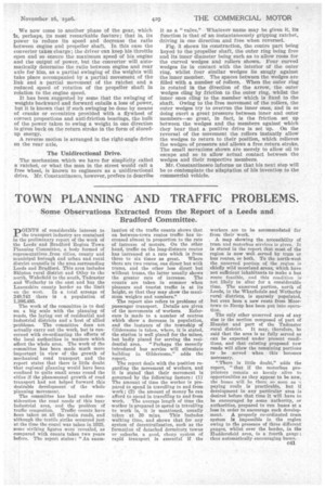
It is well known that all weights have a certain period at which they will oscillate or swing without offering any resistance to movement. Now this is exactly what these weights do when the engine is merely ticking over ; they swing gently with the movement of their eccentrics and put no pull on their temporary fulcrum, namely, the connection to the link, as shown in Fig. 4 in dotted and full lines.
When the engine speed is raised above the period at which the weights will swing with ease, the weights begin tia offer a resistance to movement, consequently there is a pull on the fulcrum at each stroke. This pull is transmitted by the link to the outer ring of the converter and sets up an oscillatory movement in the ring. When the engine is accelerated to its maximum and the resistance of the car is normal, as in running on a level road, the weights refuse to oscillate, and all the movement caused by the eccentrics is transmitted to the ring in the form of oscillations, as shown in Fig. 5.
In each of the converters is what for the moment we will call a ratchet, details of which we give later. These ratchets, being mounted on the propeller shaft, transmit movement to that shaft when moving in the direction of the arrow (Figs. 4 and 5), and move freely when rotating in the opposite direction, the free-wheel clutch of a bicycle being a simple equivalent.
It will be seen from this that each converter as it swings backward and forward will transmit an approximately constant rotary movement to the propeller shaft. We have given the two extremes, namely, the engine Idling, when no power is transmitted to the propeller shaft, and the engine at maximum speed and the lightest resistance, such as a level road, but between these c40
extremes, such as when running in traffic, one has only to decrease the power of the engine by meansof the throttle to produce any desired speed of the car between its maximum and no speed at all. We now come to another phase of the gear, which Is, Perhaps, its most remarkable feature; that is, its power to reduce its speed and decrease the ratio between engine and propeller shaft. In this case the converter takes charge; the driver can keep his throttle open and so ensure the maximum speed of his engine and the output of power, but the converter will automatically determine the ratio between engine and rear axle for him, as a partial swinging of the weights will take place accompanied by a partial movement of the link and a partial movement of the ratchet and a reduced speed of rotation of the propeller shaft in relation to the engine speed.
It has been suggested by some that the swinging of weights backward and forward entails a loss of power, but it is known that if such swinging be done by means of cranks or eccentrics provided with a flywheel of correct proportions and anti-friction bearings, the bulk of the power taken to swing a weight in one direction is given back on the return stroke in the form of Storedup energy.
A reverse motion is arranged in the right-angle drive on the rear axle.
The Unidirectional Drive.
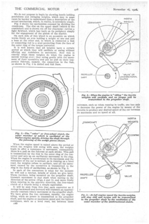
The mechanism which we have for simplicity called a ratchet, or what the man in the street would call a free wheel, is known to engineers as a unidirectional drive. Mr. Constantinesco, however, prefers to describe it as a "valve.". Whatever name may be given it, its function is that of an instantaneously gripping ratchet, driving in one direction and free when reversed.
Fig. 3 shows its construction, the centre part being keyed to the propeller shaft, the outer ring being free and its inner diameter being such as to allow room for the curved wedges and rollers shown. Four curved wedges lie in contact with the interior of the outer ring, whilst four similar wedges lie snugly against the inner member. The spaces between the wedges are filled with a number of rollers. When the outer ring is rotated in the direction of the arrow, the outer wedges cling by friction to the outer ring, whilst the inner ones cling to the member which is fixed to the shaft. Owing to the iree movement of the rollers, the outer wedges try to overrun the inner ones, and in so doing exert a great pressure between inner and outer members—so great, in fact, is the friction set up between the wedges and the members against which they bear that a positive drive is set up. On the reversal of the movement the rollers instantly allow the wedges to return to their position, which relieves the wedges of pressure and allows a free return stroke. The small serrations shown are merely to allow oil to escape and so to allow actual contact between the wedges and their respective members.
Mr. Constantinesco informs us that his next step will be to contemplate the adaptation of his invention to the commercial vehicle.