


AN INTERESTING PROPRIETARY ENGINE.
Page 50
Page 51
Page 52
If you've noticed an error in this article please click here to report it so we can fix it.
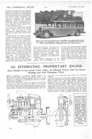
First Details of the Latest Tylor Tiger, an Efficient Power Unit for Heavy Haulage and Fast Passenger Work.
TEDI NUMBER of proprietary engines suitable for commercial-vehicle work on the British market is so limited that exceptional interest attaches to any new model which may he brought out, particularly if this be of British manufacture throughout.
One of the best-known makes of engine, of which many thousands are still in service, is the Tylor, and, taken as a whole, the power units of this make have proved remarkably reliable, although they have not been entirely free from faults, such as cracking of the cylinders between the valve caps and in the compression tap sockets, and crankshaft breakage.
However, in the new model Tyler, which is known as the Tiger and which has been entirely redesigned throughout by Tylors (J.B.4), Ltd., 134, King Street, Hammersmith, Loudon, W.6, the greatest attention has been paid to eliminating these and other small defects which the experience of years has shown to exist. At the same time the opportunity has been taken to produce an engine which, whilst being of the same bore and stroke, will develop con, siderably more power than its prototype and will, consequently, be more suited to modern conditions of Service, which demand an engine providing high power for heavy haulage,. with or without a trailer, or higher speeds in the case of passenger vehicles.
It must be remembered that the 45 b.h.p. engine of the J.B.4 type was designed and put into production 13 years ago, and it was then adopted by many •leading makers as the power unit for their commercial vehicles, and we have no doubt that` an engine founded upon the basic principles of this model will receive a hearty welcome, particularly as care has been taken, in working out its dimensions, to en-' able it to be _employed in the same sub-frames as the J.13,4 model, the only differences being in the controls and in the provision of an Autovac, all of which are included in the list price of 1220, which is subject to certain discounts according to circumstances.
Before describing this model it may he as well to state what it can do. Tests have shown that On a 4-ton lorry it gives 7 m.p.g. to 8 m.p.g. of petrol, and 700 m.p.g. to 800 roaf.g. of oil. At this point we may mention that for those who wish for further economy rather than the development of high power, the 5-in, cylinders can be replaced by others of 4k-in. bore, the stroke in each case being 6 ins. The R.A.C. rating • of the standard product is 40 h.p.
Before placing the unit on the market the makers have subjected it to months of testing on the bench, and it is now undergoing its trials in a commercial vehicle. The curves obtained on the bench show that it is in every respect a great improvement on the original model. The highest power is obtained at about 1,650 r.p.m., when 76.5 b.h.p. was shown by the Fronde dynamometer, as compared with 60.05 b.h.p. given by the standard J.B.4. The torque and M.E.P. are also welt above those on the old type, and do not drop off at low speeds in the same manner, so that the engine is able to give slow, hard pulling for hill-climbing on the higher gears ; for instance, the torque at 400 r.p.m. is approximately 290 ft.-lb. and between 600 r.p.m. and 800 r.pari. 312 ft.-lb., this comparing with 218 ft.-lb. and an average of 260 ft.-lb.
We had a run on an A.E.C. vehicle equipped with the new engine and carrying a 4-ton load, and it certainly proved most lively. Acceleration was excellent, 27 mph. was easily reached without any threshing, and the vehicle was able to get away, after slowing down on top gear, without any feeling that the engine was being forced. The particular model we tested was equipped with aluminium pistons, and these gave a slight amount of slap with the engine cold, but this entirely disappeared directly the engine had warmed up. Incidentally, castiron pistons or those of the aluminium type can he fitted according to the wish of the buyer. In the case of the cast-iron, there are three rings at the top and a scraper ring at the bottom.
The unit is governed to a normal speed of 1,300 r.p.m., but it can be run up to 1,800 r.p.m. without trouble.
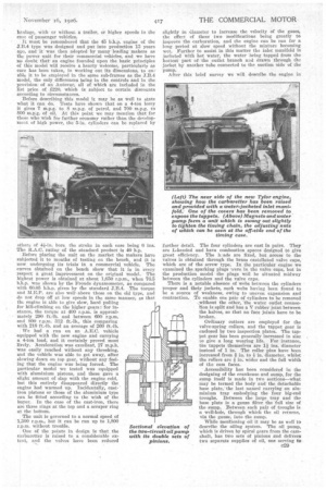
On of the points in design is that the carburetter is raised to a considerable extent, and the valves have been reduced slightly in diameter to increase the velocity of the gases, the effect of these two modifications being greatly to improve the carburation, and the engine can be run for a long period at slow speed without the mixture becoming wet. Further to assist in this matter the inlet manifold is jacketed with hot water, the water being tapped from the hottest part of the outlet branch and drawn through the jacket by another tube connected to the suction side of the pump.
After this brief survey we will describe the engine in further detail. The four cylinders are cast in pairs. They are L-headed and have combustion spaces designed to give great efficiency. The h.l.ads are fixed, but access to the valves is obtained through the brass castellated valve caps, which are of the screw type. In the particular engine we examined the sparking plugs were in the valve caps, but in the production model the plugs will be situated midway between the cylinders and the valve caps.
There is a notable absence of webs between the cylinders proper and their jackets, such webs having been found to be a source of weakness, owing to uneven expansion and contraction. To enable one pair of cylinders to he removed ,without the other, the water outlet connec 'tion is split and has a V rubber joint between the halves, so that no face joint's have to be broken.
Ordinary cotters are employed for the valve-spring collars, and the tappet gear is enclosed by two inspection plates. The tappet gear has been generally increased in size to give a long wearing life. For instance, the tappets themselves are It ins, diameter instead of 1 in. The roller pins have been increased from .0. in. to 4 in, diameter, whilst the rollers are 4 in. wider and the full width of the cam faces.
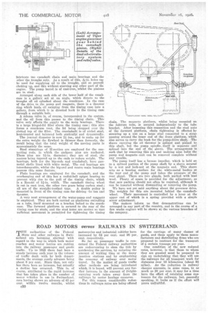
Accessibility has been considered in the designing of the crankcase and sump, for the sump itself is made in two sections—what may be termed the body and the detachable base plate, 'the last named carrying an aluminium tray embodying the four big-end troughs. Between the large tray and the base plate is a gauze filter the full size of the sump. Between each pair of troughs is a well-hole, through which the oil returns, via the gauze. into the sump.
While mentioning oil it may be as well to describe the oiling system. The oil pump, which is driven by spiral gears from the camshaft, has two sets of pinions and delivers two separate supplies of oil, one serving to lubricate the camshaft chain and main bearings and the other the troughs only. As a result of this, -j-in. holes cal be used for supplying oil to the troughs, and so prevent choking up, and this without starving any other part of that engine. The pump barrel is of cast-iron, whilst the pinions are in steel.
Arranged along each side of the lower half of the crankcase is a gallery set at an angle, which directs to the troughs all oil splashed about the crankcase. In the case of the drive to the pump and magneto, there is a thrower ring which leads oil escaping from the fiming case into a gallery, from which it is directed back o the timing case through a suitable hole.
A release valve is, of course, incorporated in the system, and the oil from this passes to the ti1ning chain. This valve only affects the supply to the maii bearings. There is a large binged-lid filler above the tan' g ease; this also forms a crankcase vent, the lid being dropped over the slotted top of the filler. The crankshaft is of nickel steel, heat-treated and balanced both statically and dynamically.
The journal diameter is now 2i ins., slid to make up for the extra weight the flywheel is thinner than formerly, the result being that the total weight of the moving parts is approximately the same.
Steel stampings of 1f-section are employed for the Connecting rods, in which the gudgeon pins are anchored. These pins are 11-in. diameter; they are of steel, the centres being tapered up to the ends to reduce weight, The bearings, both for the big-ends and crankshaft, have gunmetal shells lined with white metal. The end bearings are interchangeable, whilst the big-end and centre main bearings possess this same feature.
Plain bearings are employed for the camshaft, and the overhanging end of this has a radiahliall spigot bearing to prevent whip due to the pull of the timing chain, which is a Renold of 1i-in. width. The camshaft timing wheel is cut in cast iron, the other two gears being carbon steel ;
all are of the straight-toothed type. A double pulley is mounted in front of the timing case for driving the fan and -dynamo.
A very neat arrangement of the water-pump and magneto is employed. They are both carried on platforms swivelling on a tube, itself mounted on a bracket bolted to the crankcase. The forward platform is secured to the rear of the timing case by studs, and the stud holes are slotted so that sufficient movement is permitted for tightening the timing chain. The magneto platform, whilst being mounted on the fulcrum tube, is secured independently to the tube bracket. After loosening this connection and the stud nuts of the forward platform, chain tightening is effected by screwing up a nut on a large stud connected to a strap passing around the inner end of the front platform, which also serves to carry the bosh for the pump-drive shaft. •The sleeve carrying the oil thrower is splined and pinned to this shaft, but the pump spindle, itself is separate and splined into the end of the sleeve. The arrangement is such that by removing this pin and undoing nine bolts the pump and magneto -unit can be removed complete without any trouble.
The pump itself has a bronze impeller, which is held or to a splined portion of the pump shaft by a sleeve secured by a nut and lock-nut at the magneto end. This sleeve acts as a bearing surface for the white-metal bushes at the rear end of the pump and takes the pressure of the• rear gland. There are two glands, both packed with lead wool. Plenty of space is provided for the adjustment, so that new packing should not often be reqiiired, although it can be inserted without dismantling or removing the pump.
We have not yet said anything about thi governor drive. The weights for this are mounted behind the camshaft wheel. Their movement is controlled by a lever at the upper end of which is a spring provided with a simple screw adjustment.
The makers inform us that demonstrations can be arranged in any part of the country, and in the course of a few weeks engines will be shown at the various branches of the company.