


A Rapid Loading System
Page 64

If you've noticed an error in this article please click here to report it so we can fix it.
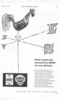
A SCHEME shown in patent No. L—k 792,098 is directed towards reducing idle vehicle time while freight is being loaded or unloaded. The basis of the scheme is the use of false platforms or containers which can be left in special loading bays while the vehicle continues on other duties. (E. Edwards, Nobold House, Featherbed Lane. Shrewsbury.)
The drawing shows a rear view of a vehicle in the loading bay. The bay comprises a pair of channel-sectioned rails (1) which are supported by legs. The removable container (shown in dotted lines) is provided with a number of rollers (2) on each side and these are positioned to suit the channels.
As the vehicle is backed into the bay, the rollers ride up ramps on the channels and lift the container clear of the vehicle which can then be driven away empty. For running, brackets on the vehicle and the container are secured by locking pins to hold the container rigidly in place.
A TIPPING TRAILER A TIPPING arrangement for a twoPi wheeled trailer is disclosed in patent No. 792,094. In this scheme, the trailer pivots as a whole about its own roadwheel axis. (Anthony Company, Streator. Illinois, U.S.A.)
The drawing shows the trailer in the discharging position. The hydraulic ram (1) which provides the lift is located on the axis of the fifth wheel or turntable (2) and is trunnioned at both ends to permit angular deflection.
The towing and braking forces are not transmitted through the turntable assembly but are taken by an H-shaped strut (3). This is pivoted at both ends and when the trailer tips, it constrains its movement and causes the road wheels to move nearer to the tractor.
The patent includes also a train of two such trailers in which the rear one rests upon a wheeled fore-carriage coupled to the back of the first trailer; PUMP FOR OPERATING TIPPING BODIES
I MPROVED performance and simplified construction are the virtues claimed for a pump shown in patent No. 792,081. Intended for operating hydraulic tipping gear, the pump works on the swash-plate principle. The subject of the patent is the arrangement of the valve gear. (Autolifts and Engineering Co., Ltd., Highfield Works, Highfield Road, Blackburn, Lancs.)
The pump is driven by the engine via spur gears (1). The end of the Z-crank (2) carries the awash plate which is prevented from rotating by a key groove (3) which nevertheless permits it to oscillate. Seven plungers are reciprocated in sequence, being coupled to the swath plate by ball-ended connecting rods (4), The valve (5) is of the rotary type and is grooved (as shown at 6) to collect the output from each plunger and deliver the liquid to the discharge port. The valve is similarly grooved on the other side to control the inlet, collecting the liquid from the space (7). Holes through the valve connect it with the outlet (8).
A RESILIENT GEARWHEEL
A GEARWHEEL shown in patent in. No. 792,330 is intended for such purposes as the timing gear, the governor drive or any other gear train in which chatter and vibration are detrimental. The novelty of the scheme is the way in which the hub part is resiliently connected to the outer ring carrying the teeth. (Caterpillar Tractor Company, 800 Davis Street, San Leandro, California, U.S.A.)
The hub and the toothed ring are mounted so that they are located in an endwise direction but are free to revolve one on the other. They are coupled by
C-shaped spring as shown at I. This is pinned to the hub at the point (2) and its other end (3) nests in a circular rect.-is in the toothed ring.
Relative movement between the two members is permitted by increasing or decreasing the curvature of the spring. The small space required for the spring renders the scheme suitable for inclusion in quite small pininns.
IMPROVED HOSE CLIPS
AHOSE CLIP is a minor component which can bring a vehicle to a standstill if it should fail. According to patent No. 791,762 (The Rover Co., Ltd„ Meteor Works, Lode Lane, Solihull. Warwickshire) some standard types of clip tend to squeeze out the rubber when hot. When cold, the rubber does not return and so leakage can eventually occur. The patent shows a design said to prevent the rubber squeezing out. —1
The bearing surface consists of a flexible metal strip (1) having diagonal cuts extending alternately from opposite sides. The strip is also provided with lugs
702.0.51, (2) which are bent round
to encircle wire rings. These rings are anchored to a screw-andnut device which forms the tensioning member.
PATENT No. 793,382 comes from Motoren-Werke Mannheim AG., Carl-Benz-Strasse, Mannheim, Germany. It shows an improved combustion chamber for oil engines. The chamber is formed in the piston crown and is egg' shaped in elevation and circular in plan. The passage leading to the cylinder is triangular with rounded corners,