


A Self-centrifuging Oil Cleaner
Page 58
If you've noticed an error in this article please click here to report it so we can fix it.
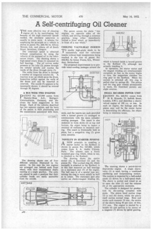
THE most effective, way of cleaning engine oil is by centrifuging, but because of the high rotational speeds needed, the necessary apparatus is usually in static units. A scheme for employing the principle on a vehicle is shown in patent No. 668,766 by Albion Motors, Ltd., and others, all of South Street, Scotstoun, Glasgow.
The rotational speed is obtained -without complication by using the velocity of the pumped oil in the lubrication circuit. The drawing shows a high-speed rotary drum (1) mounted on
ball bearings. The oil arrives under pressure at the inlet (2), passes through the tubular spindle and reaches the inside of the drum through pints (3).
The outlet from the drum is through a number of tangential nozzles (4). A reaction is set up which spins the drum. Impurities collect against the walls of the drum and can be removed at intervals. The nozzle (5) appears to be incorrectly shown; it should be rotated through 90 degrees.
A BUS WITH TWO ENGINES
PATENT No. 667,949 comes from Daimler-Benz A.G., StuttgartUnterturkheim, Germany, and discloses the latest . suggestions in bus design. Each of the vehicles described has two separate engines, and the basis of the patent is their positioning and the transmission associated with them.
The drawing shows CHIC of four different schemes illustrated in the patent. In this case the two engines are arranged one behind each front wheel, with their transmission shafts meeting at a single gearbox. The units are placed in such a position that their cylinder heads are easily accessible from the outside. The patent covers the claim "two engines, on opposite sides of the vehicle, and driving through a common gearbox, lying either immediately behind a front wheel, or immediately in front of a rear wheel."
COOLING VALVE-SEAT INSERTS
TO enable high-grade steels to be successfully used for valve-seat inserts without high temperatures being reached is the aim of patent No. 668,962, by Sulzer Freres, S.A., Winterthur, Switzerland.
The proposed improvement is to provide water-cooling passages around the seats, and the inserts arc each provided with a turned groove (1) arranged to communicate with the main cylindercooling passages. The insert is also undercut to form skirts (2) at top and bottom, the object being to impart a measure of resilience to maintain sealing. The insert is frictionally held in place, but a swaged-in ring (3) gives extra security.
NOVELTY IN STARTER PINIONS
ANEW principle in coupling a starter motor to the flywheel is shown in patent No. 667,882, which comes from S. A. Andre Citroen, Paris. The scheme uses a freely mounted gear ring which, when in use, is clutched to the flywheel.
The drawing shows the starter motor (1), a freewheel (2) and the pinion (3). The toothed ring (4), which normally is attached to the flywheel, is in this case mounted on ball bearings on a stationary part (5) of the engine. The ball race is of a special type permitting the ring to move axially as well as to rotate. The stationary part also carries an electro-magnet winding (6), which is housed inside a turned groove in the flywheel (7), although not actually touching it.
In operation, the starter motor and the magnet winding are simultaneously energized, so that, as the motor begins to turn, the magnetism clutches the ring gear to the flywheel. When the current is switched off, this ring is pulled clear by springs (8). The pinion and the ring gear remain permanently in mesh, the freewheel permits any slight overrun.
SMALL RICARDO POWER UNIT
PATENT No. 668,911 comes from H. R. Ricardo, 21, Suffolk Street, London, S.W.1, and describes a sleevevalved engine of 100 c.c. or less. In such an engine, the leakage past the piston may well be the major factor in determining the efficiency, the object being to minimize losses.
Thy drawing shows a petrol-driven four-stroke engine. A single sleevevalve (1) is used, having a combined oscillating and reciprocating motion. The motion is imparted by a ball-ended crank (2) driven by a half-speed shaft. The sleeve is ported and timed so as to open the inlet (3) and the exhaust (4) at the appropriate moments.
The cylinder is designed for production by die-casting complete with ports. The piston head carries rings
(5) to seal the sleeve, whilst the piston itself carries normal rings. Bore and stroke each measure 38 mm., the stroke of the sleeve being 40 per cent. of this, 15.2 mm. The engine is started by a handle (6) and ignition is by means of a magneto (7) driven by spiral gearing.