


MODERN GEAR 30X DESIGN
Page 50
Page 51
Page 52
If you've noticed an error in this article please click here to report it so we can fix it.
By A, W. HAIGH, A. MI. Mech.E.
WHEN a transmission designer is given the job of producing a gearbox for a new chassis, he must first determine the ratios to be employed in the box, to work in conjunction with a fixed reduction, or reductions, in the rear axle. The selection of these ratios is mostly a matter of performance, and has little connection with the design of the box itself. It is proposed, therefore, to assume that the ratios have been selected and, to 'carry on from there, to discuss the remaining steps in gearbox design, and the merits or faults of various arrangements, both existing and hypothetical.
The best relationship of gear ratios is one in which the reductions are arranged in the form of a geometric progression, i.e., each ratio is equal to the higher adjacent ratio multiplied by a common factor, for example, 1 to 1, 2 to 1, 4 to 1 and 8 to I.
When a machine is started from rest in first gear, the engine is accelerated to a speed determined either aurally by the driver, or by the speedometer. At a recognized pitch of engine noise the gear is changed to second, third and top. On changing up, if the process is to be a smooth one, the road speed attained in the lower ratio must be matched by engine speed in the higher ratio. If it be assumed that, in the short time taken to change gear, the reduction of road speed is negligible, on a level road, the geometric progression of gear ratios arranges that the matching of road and engine speeds always occurs at the same engine revolutions in any gear.
Thus, if we assume a box with ratios of 1 to 1, 2 to 1, 4 to 1 and 8 to 1, which gives road speeds of 5 m.p.h. in first, 10 m.p.h. in second and 20 m.p.h. in third gear, at an engine speed of 2,400 r.p.m., and that, in second gear, the engine speed for 5 m.p.h. is 1,200 r.p.m., then the engine speed for 10 m.p.h. in third gear, and 20 m.p.h. in top gear, will also be 1,200 r.p.m.
So, for smooth acceleration through the gears, until top is finally engaged, the engine is caused to accelerate and decelerate through exactly the Same range for all ratios, which is a distinct advantage. As the performance of an internal-combustion engine is worse at low and very high revs, than it is in the medium range, the driver can arrange the road speeds, or engine noise, at which to change gear, to come within the speed range of maximum engine performance.
One very slight disadvantage of the progressive box lies in the additional torque load imposed on the engine in top gear. Let it be assumed that the vehicle is started through the gears with constant acceleration. The force required for acceleration is, therefore, constant, rolling resistance is constant and wind resistance increased with speed. It will be appreciated that as the ratio of the gears approaches Ito 1, engine work approaches a maximum. geometrical progression. This permits of a higher thirdgear road speed, and allows top to be engaged at higher engine revs.
. In town operation, the close-ratio third' gear has been found to be of great value on private cars and light types of commercial vehicle, for, under such conditions, road speed is usually too slow to allow smooth 1-to-1 work, On heavier vehicles, which have limited excess engine power, it is doubtful whether the higher ratio of a " traffic top" is an advantage, as, with the normal progressive ratio, full power from the engine is required on many occasions in order to keep the vehicle moving.
Having decided on the gear ratios, it is the designer's task to choose the type of gears he will employ. In a four-speed box many layouts are possible, but, in the main, the disposition of the gears in the casing, and the method by which they are brought into mesh, depend largely on the type of gear used.
In an entirely "clash" box, the gears are of the straight-spur type, to faeilitate relative sideways motion between two wheels, whilst, for constant-mesh wheels, it is customary to employ either single. or double-helical gears. Thus, in a four-speed box with top and third
therefore, that, as the two subsidary forces are initiated by the tangential force, their magnitude must be dependent on it and, as the direction of one subsidary force is governed by the pressure angle, this also must be a governing factor in the strength of a gear. Knowing from the foregoing that the separating force becomes greater both with increased tangential load—which would be provided by raising the gear ratio—and increased pressure angle, it should be a simple matter to locate the various gears in the box to give optimum results. Those gears which generate the greatest separating forces should, in theory, be placed as close to the bearings as possible, whilst the pressure angle, bearing in mind only the increase in force for increased angle, should be kept as low as possible.
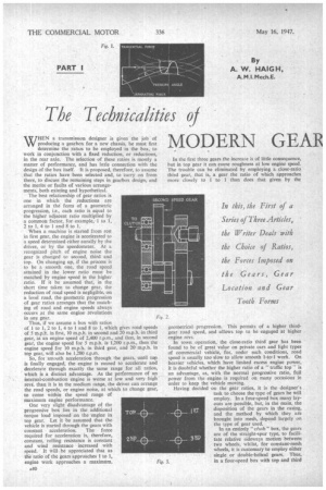
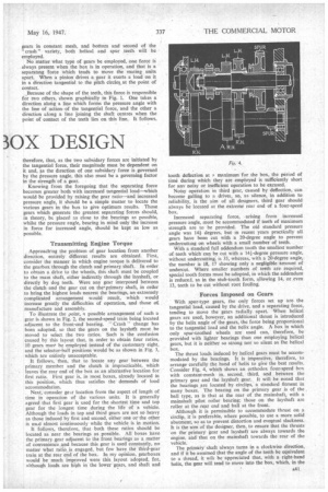
Transmitting Engine Torque Approaching the problem of gear location from another direction, entirely different results are obtained. First, consider the manner in which engine torque is delivered to the gearbox through the clutch and primary shaft. In order to obtain a drive to the wheels, this shaft must be coupled to the main shaft, either indirectly through the layshaft, or directly by dog teeth. Were any gear interposed between the clutch and the gear cut on the primaryshaft, in order to bring the highest loads nearest the bearings, an extremely complicated arrangement would result, which would increase greatly the difficulties of operation, and those of, manufacture and assembly. To illustrate the point, a possible arrangement of such a gear is shown in Fig. 2, the second-speed train being located adjacent to the front-end bearing. "Crash " change has been adopted, so that the gears on the layshaft must be moved to select the two ratios. Such is the confusion caused by this layout that, in order to obtain four ratios, 10 gears must be employed instead of the customary eight, and the selector-ball positions would be as shown in Fig. 3, which are entirely unacceptable. It follows, then, that to locate any gear' between the primary member and the clutch is impracticable, which leaves the rear end of the box as an alternative location for first ratio. First gear is, in most boxes, already located in this position, which thus satisfies the demands of load accommodation. Next, consider geir location from the aspect of length of time in operation of the various units. It is generally agreed that first gear is used for the shortest time and top gear for the longest time during the life of a vehicle. Although the loads in top and third gears are not so heavy as those induced by first and second, either one or the other is used almost continuously while the vehicle is in motion. It follows, therefore, that both these ratios should be located as near the bearings as possible. All boxes have the primary gear adjacent to the front bearings as a matter of convenience and because this gear is used constantly, no matter what ratio is, engaged, but few have the third-gear train at the rear end of the box. In my opinion, gearboxes would be much improved were this layout adopted, for, although loads are high in the lower gears, and shaft and tooth deflection at maximum for the box, the period of time during which they are employed is sufficiently short for any noisy or inefficient operation to be excused. Noisy operation in third gear, caused by deflection, can become galling to a drivel, so, as silence, in addition to reliability, is the aim of all designers, third gear should always be located at the extreme rear end of a four-speed box. Increased separating force, arising from increased pressure angle, must be accommodated if teeth of maximum strength are to be provided. The old standard pressure angle was 14i degrees, but in recent years practically all gears have been cut with a 20-degree angle to prevent undercutting on wheels with a small number of teeth. With a standard full addendum tooth the smallest number of teeth which can be cut with a 141-degree pressure angle, without undercutting, is 33, whereas, with a 20-degree angle, the number is 18, 17 showing only a negligible amount of Where ere smaller numbers of teeth are required, special tooth forms must be adopted, in which the addendum is reduced, as in the stub-tooth form, allowing 14, or even 13, teeth to be cut without root fouling.
Forces Imposed on Gears With spur-type gears, the only forces set up are the tangential load, caused by the drive, and a separating force, tending to move the gears radially apart. When helical gears are used, however, an additional thrust is introduced by the helix angle of the gears, the force being proportional to the tangential load and the helix angle. A box in which only spur-toothed wheels are used can, therefore, be
ed
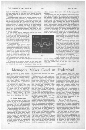
providwith lighter bearings than one employing helical gears, but it is neither so strong nor so silent as the helical box. The thrust loads induced by helical gears must be accommodated by the bearings. It is imperative, therefore, to arrange carefully the hand of helix to give the best results. Consider Fig. 4, which shows an orthodox four-speed box with constant-mesh in second, third. and between the primary gear and the layshaft gear. It will be noted that the bearings are located by circlips, a standard finnent in many, boxes. The bearing on the primary gear is of the. ball type, as is that at the rear of the mainshaft, with a mainshaft pilot roller bearing; those on the layshaft are roller at the rear end and ball at the front. Although it is permissible to accommodate thrust on a circlip. it is preferable, where possible, to use a more solid abutment, so as to prevent distortion and eventual slackness. It is the aim of the designer, then, to ensure that the thrusts on the primary gear and layshaft are always towards the engine, and that on the mainshaft towards the rear of the vehicle. The primary shaft always turns in a clockwise direction, and if it be assumed that the angle of the teeth be equivalent to a thread, it will be appreciated that, with a right-hand helix, the gear will tend to move into the box, which, in the
event of circlip failure, would be disastrous, and, with a left-hand angle, out ot the box in the desired direction. The helix angle of the primary gear must, therefore, be left-handed.
The constant-mesh wheel on the layshaft, mating with the primary gear, must, obviously, be right-handed in order that it will run with its mate. The thrust, however, is in the incorrect direction, that is, towards the rear of the box.
Now consider wheel A, which is the layshaft gear of the third-speed train: It always revolves in an anti-clockwise direction, so, if its tendency is to move or thrust towards the front of the box, it must have a right-hand helix. This means that the third-speed mainshaft gear must be lefthanded and thrust towards the rear end of the box, which is what is required.
As the primary train is constantly working, no matter what gear be engaged, there is always a thrust in the layshaft towards the rear of the box. But the thrust loads, induced in the layshaft by second and third gears, are always greater than that induced by -the primary train, and the resultant load on the rear bearing is in the correct direction.
Double-helical gears, that is, gears which might be considered as two single helicals placed back to back, possess the advantage of cancelling out all thrust loads, half of the gear exerting an equal thrust in the opposite direction to that set up by its fellow. Because of the limits of accuracy to which the halflength of the teeth must be held, these gears etre expensive to produce and, for this reason, are little used in the cheaper and medium-piked vehicles.
In additien to the forces exerted on the shafts and bearings by the various types of gear, other factors affecting the choice of teeth must be considered. What are the relative strengths of the teeth? • How do they compare for quietness?
Straight-spur teeth are the weakest and noisiest of the three types, although it is possible, by accurate finishing and assembly, together with tooth-profile corrections, to ensure almost complete silence in operation. • Comparing a straight tooth with one of helical form reveals the obvious facts that the latter is longer and, because it follows the circumference of the gear, it is not merely a straight bar of metal. That a helical tooth is stronger than a straight one for equal gear width cannot, then, be denied, in addition to which attribute it is also quieter and smoother in operation.
Consider the actkn of two involute teeth during the time they are in mesh (Fig. 5). If A he the driver, the first contact is made w:th a tooth in B at its extreme tip. So soon as this contact is made, load is applied along the whole length of a spur tooth, which means that, as each tooth on the driven wheel reaches the position of the tooth shown, it will be subjected to an immediate load.
Whilst it is true that the tooth at this juncture does not take the whole load, other teeth being in mesh, the action of two meshing straight-spur gears can he said to result in a series of shocks to the teeth. A helical gear, on the other hand, smooths out this action, as will be appreciated if it be assumed that the gear is composed of a number of extremely thin spur gears, each being staggered from its neighbour.
By the time the leading end of the tooth is coming out of mesh the trailing end is entering, and helix angles are usually so arranged that the trailing end of one tooth is still well in mesh when the leading end of the next tooth comes into operation.
(To be continued)