


REAR .AXLE DESIGN,
Page 32
If you've noticed an error in this article please click here to report it so we can fix it.
A Résumé of Recently Published Patents.
We are accustomed to designs of rear axle in which,the main driving and the differential .gears are so mounted that • they can be withdrawn entire for inspection, overhaul, adjustment or repair, the said withdrawal being possible with. out any disturbance of the remain
ing details of the axle. In the ,construction which is embodied in specification No. 155,1.96, we are, however,
carried a. stepfarther. The easing-in which these parts are supported is mado oil-tight, the holes therefrom for • the emergence of the driving and axle shafts being stopped by felt-packed rings. Not only does this enable parts to be withdrawn without there being any necessity first of all to drain away some of the lubricant, but it also eliminates entirely any chance of the oil travelling along the axle easing ancbescaping on to the brake drums, wheels and tyres. The patentee is Argus Motoren-Gesellschaft M.B.H.
Other Patents of Interest.
The-braking mechanism which.is described by. M. Stringer and others, in specification No. 156,588, applies to cars or lorries on which both brakes operate on drums on the rear wheels. It embotlie,s.an arrangement of cables devised to allow of either foot or hand, brake operating both sets of brakes simultaneously, suitable compensating devices being • provided to ensure even application of both brakes to both wheels. Neither brabe.interferes with the other, and both brakes maybe applied either together or successively with cumulative effect.
• Spuds which automatically projeet through and withdraw within the rim of the tractor wheel are described in specification No. 172,273, by G Szakats. Each spud is spade-shaped and is mounted on 'the end of a curved or hook. shaped lever, which is pivoted at ite other end on the angle-irons which stiffen the wheel rim. Ea-Ch of these levers is coupled by a connecting rod which is attached to an eccentric, itself mounted on a crankpin on the tractor axle. As the wheel revolves, those spuds in the lower half are caused to project through holes in the rim, some of them piercing the ground and doing their part in propelling the tractor. The others are withdrawn, and as they are withdrawn the forward sides are scraped against. the edge of the hole in the rim end thus cleared of ;any soil or earth which may be adhering to them. The rim of the wheel itself is also shaped to facilitate and .assist the gripping action of the spuds, a shallow trough being formed behind each spud,' into which the earth which 'is pushed aside on entry of tho spud into the ground may climb.
Fe R. Sutcliffe moUnts, between carburetter and induction manifold, a casing about 12 ins. diameter by.3 ins. deep,. which is packed with absorbent end carbonaceous substance. The effect is to fetter the explosive mixture and to retain any liquid which it may contain. The absorbent substance must, for its proper operation, be maintained at a temperature not. exceeding 200 deg, C„ and for this purpose the heat of the exhaust gases is-utiliied. The device is fully %described in patent specification No. 177,552.
No. 1.77,698, by F. C. Allworth, describes a mechanical engine-starter whichiis capable of being operated by the driver'from the driving seat. There are two.cords,•both of which are secured at one end to the startinghandle, the other ends being located near the steering pillar. Pulling on one cord brings t or starting handle into engagement, partialb rotatinglit at the same time, so that it is placed in the " ready " position. A pull on the other cord then rotates the crankshaft, and, if everything is in oraer,starts the engine.
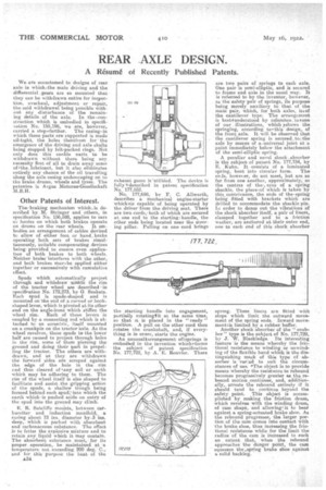
An unusualtarrangernent ogsprings is embodied in the invention whichforms the subject • of patent specification No. 177,722, by A. E. Rouvier. There
are two pairs of springs to each axle. One pair is semi-elliptic, and is secured to frame and axle in the usual way. It is referred to by the inventor? however, as the safety pair of springs, its purpose being merely auxiliary to' that of the main pair, which, for both axles, isiof the cantilever type. The arrangement is bestrunderstood by reference. toeone of our illustrations, which ,sshoors the springing, according toethis design, of the front axle. It will be observed that the cantilever spring is secured,toothe axle by means of a.universaI joint. at'a point immediately below the attachment of the semi-elliptic spring.
A peculiar and novel shock .absorber is the subject of patent No. 177,734, by E. Kuhn. It consists of a laminated spring, bent into circular form. The ertis, howeier, do not meet, but are as far from one another, approximately, as the centres of the., eyes of a spring shackle, the placeiof which is taken by this contrivance, the ends of the-spring being fitted with brackets which are drilled to accommodate the shackle pin. In order to damn out the vibrations Of the shock absorber itself, a pair of liners, clamped together and to a friction washer, are anchored at their outer end, one to each end of this shock absorber spring, These liners are fitted 'with stops which limit the outward movement of the spring ends. Inward movernentiis limited by a rubber buffer.
Another shock absorber of the " snubber" type is the subject of No. 177,728, by J. W. Blackledge. Its interesting feature 'is the means whereby the frictional resistance to winding or unwinding of the flexible band which is the distinguishing mark of this type of absorber is vae_ed to suit tins circumstances of use. "The object is to provide means whereby the resistance to rebound becomes progressively greater as the rebound motion continues, and, additionally, arrests the rebound entirely if it should tend to continue beyond the safety point. This object is accomplished by making the friction drum, which revolves with the winding drum, of cam shape, and allowing, it to bear against a spring-actuated brake shoe. As the rebound progresses, the larger portion of the cam conaee into contact with the brake shoe, thus increasing the frictional resistance while for the limit the radius of the cam is increased to such an extent that, when the rebound approaches the danger point, the cam squeezes the ,spring brake shoe against a solid backing. •