


Automatic Advance for Fuel-injection Pumps
Page 38
If you've noticed an error in this article please click here to report it so we can fix it.
AN invention of some importance-an automatic-advance device for fuel-injection pumps on oil engines— has just been brought to a practical stage, in France, by the S.E.V. Magneto concern. The constantly varying load on high-speed compressionignition engines employed in road vehicles necessitates a large measure of flexibility and, in this respect, the advantages of an automatic-advance system are apparent.
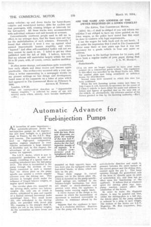
The S.E.V. device, which is now in commercial production, is neat and simple, consisting of a special form of coupling introduced into the fuel-pump drive. The drive is transmitted to the pump through the medium of two plates, connected in such a manner that the driven plate on the pump spindle can assume a certain angular advance over the driving one. This advance is brought about under the influence of hinged balance weights, as engine speed increases.
The circular plate (A), mounted on the driving shaft, carries two balance weights (X), only one of which is shown, articulated to pins and capable of a limited outward movement under centrifugal force. Two small levers (D), also articulated to the drivingplate, are provided with dowel pins
(E), engaging in the straight slots K, which are cut in the balance weights. At the extremities of these levers and B28
mounted on their opposite faces, are two more pins (L) equipped with small four-sided blocks, or shoes, which can turn on the pin.
• These shoes engage in curved grooves, cut in the driven plate (M), which is mounted on the pump spindle.. Small springs are included in the balance-weight mechanism, but these act simply as shock-absorbers and prevent noise when the appliance is running under varying engine loads.
A clever feature of the design is the manner in which the transmission of movement is rendered irreversible in relation to resistance offered by the pump.
Suppose that the appliance is turning in a clockwise direction. Reaction from the pump will thus operate in an
anti-clockwise direction and result in pressure between the outer surface of the curved groove and the sliding shoe, centred upon the pin L. This force operates through the geometrical axis of the lever D, directly upon its joint of articulation (C), and thus has no effect upon the functioning of the appliance. It follows that at whatever speed the driving plate may turn, pump reaction cannot affect the orientation of the levers.
In order to make the diagrams clearer, it may be pointed out that, whilst the driving-plate is a full disc, the driven plate on the pump spindle is reduced to a strip to save weight. The makers of the device are S.E.V. Magnetos, 26, Rue Guynemer, Issy, Seine, France.