


Semi-trailer
Page 52
If you've noticed an error in this article please click here to report it so we can fix it.
With Hydraulic Steering 'TO make all wheels of a semi-trailer J. outOt partake of the steering movement, is the aim of a scheme shown in patent No, 636,135, by N, V. Hu!sem°, Arnhem, Holland. The controlling factor in. the arrangement is deflection of the,trailer with respect to the tractor, this . is hydraulically translated into steering movement of the tear axle or ax
In the drawing, .1 represents the rear end. of the tractor; this is fitted with a fixed gear (2). Meshing with this gear are a pair of racks (3) carried on the trailer. As the tractor turns, one of the racks advances whilst the other retards, and the movement is transmitted to a pair of hydraulic cylinders (4), which are piped to follower cylinders (5).
The latter are connected to. conventional . steering arms. (6) on the rear axles, the geometry being such that the correct steering angle is obtained.
ADJUSTING SUSPENSION TO THE LOAD
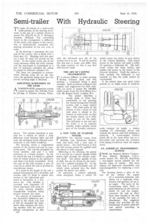
A TORSION-ROD suspension system fl.comes in patent No. 636,266, from -Eividge, 8, Elmtree Avenue, Esher,
Surrey. The scheme described is suitable for a • vehicle in which a wide difference exists between light and full load, the-springing being adjusted automatically to suit either condition.
The drawing shows a longitudinal section of the torsion-rod and its associated parts. The rod lies alongside the frame member, and end 1 is held stationary in a' frame bracket. At the far end of the rod, it is fitted to a splined tube (2) which returns to the stationary end where it is freely journalled. From this end of the tube projects a pair of arms (3) to which the axle is pivoted by conventional means.
At' a point in the length of the rod, a splined enlargement (4) is Provided, and another tube (5) fitted to splines also returns to 'the right-hand. end where it terminates in a free sleeve (6). This Member is provided with dog-teeth (7) which intermesh with teeth on the main moving member, considerablebacklash being present between the teeth.
The amount of backlash is the 'maximum -deflectiOn permitted. to -the Whole rod, and ifthis be exceeded the inner sleeve then connects the mov"ing member with the central splined enlargement so that
A42. only the left-hand part (8) of the torsion rod is in use. It will be noticed that this part is larger and stiffer than the inner portion, so that it can deal with heavier loads. .
• THE ART OF CASTING CRANKSHAFT'S TT is always difficult to make castings having alternate thick and thin sections, a crankshaft being a good example. Some problems arising in this respect, and suggestions for their solution, are given in patent No. 636,096, which comes from the Ford Motor Co., Ltd., 88, Regent Street, London, WA.
The -patent describes a mould made to form four crankshafts at one pouring, the mould having four formed cavities and a large' central riser. The chief point of the scheme is that a piece of cold steel plate is placed at the bottom of each cavity, so that the molten metal, as it falls, comes to rest on the plate. The chill-plate is not cast into the work; it is an external member which actually forms part of the foundry conveyor.
A NEW TYPE OF STARTER MOTOR
PATENT No. 636,224 comes from Scintilla, Ltd., Solothurn, Switzerland, and deals with a new type of starter motor. The chief feature is that the full current cannot be applied until the. pinion is fully engaged.
Referring to the drawing, the pinion (I) is carried on a central spindle which passes right through the tubular armature shaft. The pinion spindle is free to slide, but can be driven by the armature via a splined coupling (2). At the back end is a 'quick-threaded rod (3) which,' when screwed into the shaft, pushes the pinion into mesh. In operation, a control solenoid, when energized, closes a switch (4)
which causes the motor to turn sloWly in the reverse direction. Thisaetian screws in the 'central rod until a'collar (5) operates a bellcrank (6). The bellcrank works the main switch, and applies full power to the motor in the forward direction. Until the pinion is fully meshed, the bellcrank is not reached, so that the teeth cannot be overstressed.
If the pinion does not mesh when pushed in, as might occur if tooth-tb
tooth 'contact made; a clicker coupling (7) alternately drives and releases the pininn until full meshing -is achieved. A: screw-loaded friction clutch(8) in the main, drive acts ,as a free-wheel and prevents the armature from.being :overdriven when the engine starts.
AN, AMERICAN TRANSMISSION SYSTEM..
F. ROM. the ,General Motors Corpora F. ROM. the ,General Motors Corpora
lion, Detroit, Michigan,. , U.S.A., comes Patent . No. 636,139, describing a rear-engine layout suitable for the heavier types of vehicle. The main objects -are improved accessibility and interchangeability for replacing a worn Unit.
The drawingshows a plan of the rear of the vehicle; the engine (I) is mounted crosswise, and drives via a hydraulic transmission and gearbox (2) set at an angle. The parts of the transmission most likely to need attention are the one-way clutch (3) and the torqueconverter (4) and . so these have been located at the end of the assembly for ease of detachment. The suggested design also provides for the interchange of power units-(oil and petrol) according to requirements.