


Power-operated Clutch and Gearbox
Page 36
If you've noticed an error in this article please click here to report it so we can fix it.
A Re:swne of Patent Specifications That Have Recently Been Published ACLUTCH and gearbox, in both of which engagement is performed by hydraulic or magnetic means, are shown in patent No. 560,379, by H. Hobbs, 28, Woodcote Road, Leamington Spa. The patent is illustrated by an example working on the hydraulic principle.
The drawing shows the clutch imployed in the system; it is fitted with two output discs (1 and 2), which are carried by two output shafts (3 and 4), one of which is a tube surrounding the other. Engagement is performed by energizing one or other of the two hydraulic expanders (5' or 6); these press their plates into contact with the driven diics and drive one or the other as selected. The two output shafts lead to a gearbox having sliding dogs operated, similarly, by hydraulic mechanism; the specification also illustrates this unit. The stated object is to allow gear changing to be performed with a minimum of 'manila' effort without bulky mechanism. '
PNEUMATIC SERVO-MOTOR WITHOUT RETURN SPRINGS
PATENT No. 560,228 comes from Clayton Dewandre Co., Ltd., and J. Rodway, both of Titanic Works, Lincoln, and discloses a servo-mptor suitable for operating clutches or brakes. The motive power, in this case, is compressed air, and the novelty resides in the absence of any form of return spring for the piston.
The device comprises a large cylinder mounted concentrically with a smaller one (1). A large piston (2) 's carried on a tubular member (3) , which is extended into the small cylirtder, where it forms a second piston (4). This piston houses the gudgeon in that carries the connecting-rod (5). which forms the output member, sufficient working clearance being provided inside the tube (3).
The large piston is powered by the admission of air, via a control valve (6), to • the right-hand space; this moves the piston to the left, expelling the air on the other side out of a permanent atmospheric port (7). The duty of a return spring is performed by the small piston (4); this is permanently connected to the air supply via a port (8) and is, therefore, always biased by air pressure. HYDRAULIC TRANSMISSION WITH AUTOMATIC LOCK-UP
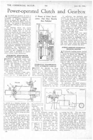
DATENT No. 560,256, by Borg
Warner Corporation, Chicago, Illinois, U.S.A., deals with a transmission gear of the torque-converter type. The chief feature of the patent lies in a means for automatically establishing a positive drive in the top-gear condition. Although t h e patent shows the actual construction, the principle is better illustrated by the dia gramma tic sketch shown herewith.'
In this, the engine shaft (1) is connected to one of the hydraulic runners (2), also to a free-wheel clutch (3) which transmits only forward drive. The other runner (4) is attached to the output shaft (5). In series with the free wheel is a centrifugally operated
d o'g clutch (6) which, with the free wheel, provides an alternative 'drive from that of the hydraulic mechanism. In operation, the hydraulic gear handles the drive at 'low speeds but, at a certain predetermined speed, the centrifugal dogs --(7) move outwards. They do not necessarily engage with their mating notches, as they are provided with saw-tooth ends which simply ratchet over the opposite teeth. By a momentary reversal of torque, however, the dogs will engage and establish a through drive.
When the speed falls once again below the critical value, the dogs (7) tend to return but, being under load, would be unable to disengage were it not for the free wheel (3). This, being unable to transmit power in the coasting sense, relieves the load from the dog teeth, afterwhich the hydraulic gear once again assumes the drive.
POWER-ASSISTED HYDRAULIC BRAKING SYSTEM
AN hydraulic braking system, having a suction-operated booster cylinder, is shown in patent No. 559,921, by I3endix Aviation Corporation, South• Bend, Indiana, U.S.A. An improved version of an earlier design, the main object is to give the driver an increased sense of " feel " on the brake pedal.
The drawing shows the whole system in outline, with the control valve in detail. One lead of the pedal pipe (4) goes to the control valve, whilst the other, as an emergency measure, leads directly to the master cylinder (5). The booster cylinder (7) contains a piston which is subjected to engine suction on both sides via pipe 3 lead
ing to the induction n The suction on the left-hand side is applied via pipes 8 and 9, which are connected inside the control valve.
In operation, the pedal pressure, arriving at the control valve, actuates a small piston(12). which presses on
a rocking bar (1). This bar closes
the suction line 'by means of a disc valve (11) and opens an atmospheric port (2), which destroys the vacuum or, the left-hand side of the booster, and thus causes the piston to operate
the master cylinder (5). The main feature of the design lies in the use of a small hydraulic piston (10) which is piped (via 6) to the high-pressure fluid system. This piston exerts an opposing force on piston.12, thus increasing pedal resistance.