


Simple Design of
Page 60
If you've noticed an error in this article please click here to report it so we can fix it.
Automatic Advance Mechanism
1"(obviate e use of links, levers th ) and pivots, all of which are liable to wear, is the chief object of the design of automatic-advance mechanism, for injection pumps, shown in patent No. 505,074 by A. Bird and Henry Meadows, Ltd., Fallings Park, Wolverhampton. The drawing shows a section of the operative part of the device; this comprises a pair of driving dogs (2) interspaced with a driven pair (3). The motion is transmitted via weights (I) which, under the influence of centrifugal force, can move radially and so increase the angular distance between the two components. By a suitable formation of the cam surfaces (4) any desired characteristic of regulation can be obtained.
Progress in Rotary-valve Design.
FOR many years much research into the possibilities of rotary valves has been undertaken by R. Cross, 33, Midford Road, Combe Down, Bath, and in patent No. 504,709 is shown this inventor's latest developments. One of the major problems is to seal the rotating barrel, and whilst the cylinder pressure can be of use in this respect, it may have to be modified in order to prevent excessive pressure on the
barre . The patent deals with a means for achieving this.
The rotary valve (4) is housed in a two-piece structure, both members (1 and 3) of which are floating. The compression forces act upwardly on the barrel (4) and the inner member (1); the latter transfers its pressure to a number of levers (2) which, as a result, tend to move the outer casing (3) downward. This action eases the load on the rotary valve, at the same time retaining a proportion of the pressure to act as a seal.
Other details of this interesting engine have been disclosed in earlier patents, numbered as follow:. 423,474, 451,917, 467,620, 474,521, 479,539 and 481,933 New Principle of Engine Mounting.
PATENT NO. 504,919 shows an engine mounting in which the torque reaction is automatically cancelled out by shifting the engine to a new position under full load. The patentees are Leyland Motors, Ltd., Kingston-upon-Thames, and others.
The drawing shows the outline of an engine intended to be mounted with its cylinder axes in a horizontal plane. At rest, the line A-A passes through the centre of gravity, and represents, at its ends, the position of the engine supports. At full load the engine moves to a new position, so that the line of support, now B-B, no longer passes through the centre of gravity, but is so offset that the out-of-balance force equals that of the engine torque.
The method of permitting this movement is to arrange the mountings in the form of rockers which can roll along the surface of their housings. This means that the universal joint has a slight misalignment to accommodate, although another scheme provides for twice the travel at only the front end.
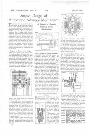
An Unusually Compact Injection Nozzle.
PATENT NO. 504,875 comes from Daimler-Benz A.G., Stuttgart, Germany, and discloses a new design of
injector. T h novelty lies in its construction rather than in principle, the object being to produce an injector no larger than a normal sparking plug.
Externally, the. body ,(5) resembles that of a sparking plug, but carries an upper screwed portion over which fits a cap-nut (6). This clamps three joints, the washer (1), the pipe nipple (2), and a face-seating under the loose cup (3); this arrangement relieves the screw thread of the fuel pressure.
The central needle has a mushroom head (4) and is spring-loaded in the usual manner. The needle and spring are quite clear of their surroundings, so that the conical seating must eventually become spherical.
An Electrically Heated Carburetter.
A CARBURETTER, said to be .1—t equally suitable.for petrol or heavy fuels, is shown in patent No. 504,871 by E. Stadler, Ankengasse 4, Zurich, Switzerland. The chief novelty lies in the use of electric heating for both the fuel and the mixture. Referring to the drawing, the fuel reaches the venturi via a ring of small ports located in the middle of the venturi, the latter being made in two parts, an upper ring (1) and a lower ring (3). The heating coil (2) surrounds the lower half; in this position it heats, not only the tube but, in addition, the liquid fuel in an adjoining annular space (5).
The conical obturator (4) is moved , in unison with the throttle valve, the object being to maintain a uniform strength of mixture at all speeds.