


AN ENGINE FOR HIGH AND LOW SPEEDS.
Page 30
If you've noticed an error in this article please click here to report it so we can fix it.
A Resume of Recently Published
Patent Specifications.
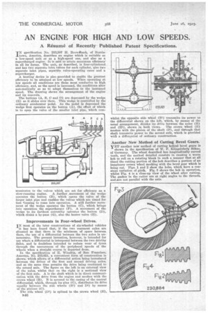
INspecification No. 233,507 H. Brow-Aback, of Norristown, America, describes an engine which is suitable as a low-speed unit or as a high-speed one, and also as a supercharged engine. It is said to attain maximum efficiency' in all its forms. The unit, as described, is four-cylindered. and has two separate inlet valves for each cylinder, also two separate inlet pipes, separate valve-operating cams and a supercharger.
A heating device is also ,provided to enable the greatest efficiency to be attained at low speeds. When operating at low speeds all conditions are those most conducive to high efficiency, and, as the speed is increased, the conditions alter automatically so as to adapt themselves to the increased speed. The drawing shows the arrangement of the engine and its controls.
The buttons (A, B, 0 and D) are depressed by the wedge (E) as it slides over them. This wedge is controlled by the ordinary accelerator pedal. As the pedal is depressed the wedge first operates on the button (A), the effect of which is to open the valve of the smaller inlet pipe, which coin municates to the valves which are set for efficiency as a slow-running engine. A further movement of the wedge operates the button (B), which opens the valve of the larger inlet pipe and enables the valves which are timed for fast sunning to come into operation. A still further movement of the wedge operates the button (0), which brings into operation the supercharger (F). A movement of the wedge to its farthest extremity operates the button (D), which closes a by-pass (G), also the heater valve (H).
Improvements in Four-wheel Drives.
IN most of the later constructions of six-wheeled vehicles it has been found that, if the two rearmost axles are situated E0 that there is the minimum of space between them, the use of a differential between the two axles is unnecessary. The present invention, however, is intended for use where a differential is interposed between the two driving Yxles, and is doubtless intended to reduce wear of tyres through the unevenness of the peripheral speeds of the wheels when a straight course is departed from.
In the specification of E. Winship, of San Francisco, America, No. 233021, a convenient form of construction is shown, which allows of a differential action being introduced between the drives of the first and second driving axles, and at the same time permits the drive being continued to the second axle. The figure on the left is an external view of the axles, whilst that on the right is a sectional view of the first axle. A is the shaft which is in direct communication with the drive from the engine and meshes with the crown wheel (B). B is secured to the casing of the central differential, which, through its pins (G), distributes its drive equally between the side wheels (111) and Di) by means of the pinions (C).
The side wheel (Di) is splined to the crown wheel (E),
whilst the opposite side wheel (31) transmits its power to the differential shown on the left, which, by means of the usual arrangement, divides its drive between the axles (H) and (Hi), shown in both views. The crown wheel (E) meshes with the pinion of the shaft (F), and through that shaft transmits power to the second axle, which is provided witIt a differential of ordinary construction.
Another New Method of Cutting Bevel Gears.
yET another new method of cutting helical bevel gears is
shown in the specification of W. F. Slingelnbeit Siihne, of Germany. The wheel described has longitudinally curved teeth, and the method detailed consists in causing a worm hob to roll on a rotating blank in such a manner that at all time the cutting portion of the hob describes a portion of an imaginary crown wheel meshing with the bevel gear which is being cut. Figs. 1 and 2 show the hobs, which have a constant variation of pitch. Fig. 3 shows the hob in operation, whilst Fig. 4 is a close-up view of the wheel after cutting. The gashes in the cutter are at right angles to the threads, and ore not parallel with the axis,