


SOME REPAIR ITEMS AND HINTS.
Page 29
If you've noticed an error in this article please click here to report it so we can fix it.
Practical Points Suggested by Our Driver and Mechanic Readers.
THE repair of a punctured carburett,er float is an occurrence which has to be dealt with at fairly frequent intervals by those whose daily work lies in a garage or fleet workshop, and the job is not always so simple as it seems at first sight. "TM.," of Brighton, de
scribes the method which he follows in cases of this description, for which this week's prize of 15s. has been awarded.
Care is necessary when applying a soldering iron to a defective float to see that the heat transferred to the float does not cause the air to rush out of it and after repair give rise to buckling, -which is easily caused, owing to the thin metal of which the float is made.
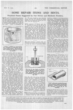
The principal point of " advice is to place the float in a basin of water in such a manner that only the portion to be repaired projects above the
surface. A weight will help to hold down the float, and a small wooden block or similar object can be placed under on side of it to raise the damaged portion above the water.
To find the source of the leakage of petrol, the float is immersed in hot water, and a stream of bubbles indicates the defeetiv4 area. The next procedure is to remove the petrol which is inside the float by piercing a small hole close to one edge. By blowing into the float and quickly turning it upside down, the pressure will force out the liquid inside. Repeating this operation a few times will clear the float entirely ; the portion surrounding the hole is cleaned prior to soldering. The draining hole should be repaired last ; but, of course, care should be taken to see that the orifice is blocked when repairing the original leak to prevent the ingress of water when the float is immersed.
For cracks and large leaks a patch of thin stencil brass, about .002 in. thick, will suffice. The surface should be cleaned up and the surplus solder wiped off. The same should be done with the patch, and the two should be joined together by drawing the patch over the float with the soldering bit.
THE majority of drivers and me
chanics are aware of the old tip of placing a nut or a small piece of iron beween the valve cap and the head of a valve which has to have the spring removed in order that it may be kept upon its seating during the spring-lifting operations. " H.A.," of Preston, also suggests that this method be followed when it is desired to unscrew the nuts which locate the valve springs on a Leyland vehicle. If the cap be screwed down fairly tight, the valve will be prevented from rotating when the spanner is applied to the nuts on the valve stem.
IN some instances gudgeon pins are fixed in the small ends of the connecting rods by means of setscrews which
damp the split ends of the rods firmly around the pins. Difficulty is experienced in some instances in holding the piston and connecting-rod assembly firmly while undoing an obstinate setscrew. According to " W.C.," of Stockport, two bolts should be obtained which fit inside the gudgeon pin, so that the hexagon heads abut firmly against the ends of the pin. The assembly is then placed in a vice, the bolts being nipped between the jaws of the vice, thus putting considerable pressure upon the gudgeon pin in a longitudinal direction.
THE coiled outer casing of speedometer drives occasionally breaks, either due to vibration when the cable is unsup
ported or perhaps to its being accidentally pulled. An apparently efficient and cheap method of repair is suggested by
E.C.," of Nuneaton. The cable is detached and a piece of copper tubing selected of approximately If ins, length, the internal diameter being such that it will pass over the broken ends which have to be joined together. The inner cable has to be removed. In all probability one of the couplings at the end will have to be unsoldered in order that the cable may be removed and reinserted when the repair is finished. Presuming that the inner portion has been removed, the copper tube is slipped over the ends, which are then pushed together, the copper pipe being slid along until it covers an equal length of each end of the outer easing.
Place the copper tube in a vice and squeeze it together by gentle pressure of the jaws, subsequently filing the copr,P7 tube to remove any sharp edges, efe. The inner cable should be replaced anti the end resoldered into position. It is desirable, when fixing the cable on the vehicle, that the repaired portion be so placed that no acute bend occurs close to the end of the copper tube, otherwise a fracture may occur at some future date, due to the excessive strain imposed on a small area of the flexible casing.
THE purchase or manufacture of re placement bushes is not always possible in the very short space of time which may be available for vehicle repair. " R.H.," of Trowbridge, suggests a practice which he has found of service in such circumstances.
The bush is sawn through at one point parallel to its axis and closed up, the thickness of the saw-cut being the available space for contraction. The internal diameter of the bush will, of course, be reduced ; but so will the external diameter, and it is therefore necessary to wrap tinfoil or similar material around the outside of the bush to ensure it fitting tightly into the housing when replaced.