


AN EMERGENCY MOBILE ROAD BREAKER.
Page 20
Page 21
Page 22
If you've noticed an error in this article please click here to report it so we can fix it.
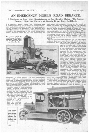
A Machine to Deal with Breakdowns in Gas Service Mains. The Latest Product from the Factory of Dennis Bros., Ltd., Guildford.
IN districts where there are extensive gas systems provision has to be made by the responsible authorities, whether private or municipal, for dealing quickly and efli,ciently with leakages and other breakdowns in the service. These are usually caused by the subsidence of the earth beneath the mains, allowing them to sag and ultimately to fracture. If If such defects are not immediately dealt with, an explosion may occur, probably resulting in considerable damage to the roadway and adjoining property, with possible injury to persons or loss of life. Many will doubtless recall the explosion which occurred some time ago in a street in South-east London, from a similar cause to that mentioned above. Usually, however, when there is a fracture in a main the surface of the roadway is undamaged, the escaping gas reaching the surface through manhole covers, gratings, etc. So soon as a leakage is reported, the superintendent in charge of the mains loses no time in getting men and tools at work to discover and repair the damage. Owing to the speed at which the work has to be carried out, the method of breaking up the roadway by driving steel wedges into it by manual labour is found to be toe slow on the modern hard-surfaced streets, and pneumatic picks are used for this purpose. These -tools are supplied with air from a slow-speed reciprocating compressor, which is driven through suitable gearing by a petrol engine, the two units being mounted on a steel frame on small wheels.
These machines are excellent for the duty they perform, but have one drawback when used for excavation work of this kind, namely, the necessarily slow speed at which they can be transported. When a defect in the gas system is reported a lorry is brought into the depot, loaded up with men and tools, coupled to the compressor outfit, and proceeds to the scene of trouble. It will be readily understood that when this occurs on the outskirts of a district covering a large radius, considerable time has elapsed before the machine reaches its destination. This is, of course, an undesirable feature, as the question of time in which the fault can be corrected is of paramount importance. Chiefly because of this drawback, gas engineers have turned their attention to the question of a self-contained vehicle as a means of carrying out this work in a more efficient manner. It is expected that, with the appliance here described, from two to three hours delay will be avoided.
The South Metropolitan Gas Co., whose system covers the greater part of South London, have recently taken delivery of such a machine from the well-known Guildford firm of Dennis Bros.,
ervr fz
IAAF €.1 Y Limited. A description of the vehiele will be of particular inlate, .3t to those who make use of portable pneumatic tool outfits.
The chassis is the makers' latest 2-ton type, being extremely sturdy and neat in appearance. The engine has a bore of /15 ram. and a stroke of 150 mm., developing 45 b.h.p. The compressor, manufactured by Reavell and Co., Ltd., of Ipswich, is one of their quadruplex type, with a bore of 7 ins, and a stroke of 5i ins., capable of delivering 210 cubic ft. of air at 100 lb. pressure per sq. in. per minute, at 425 revolutions, requiring 37 b.h.p. at the driving shaft. The speed of the engine at this output is 1,200 revolutions per minute, which necessitates a gear reduction of approximately 3-1. The primary drive is taken from an extension of the road gearbox, being transmitted by a flexible coupling and short shaft to the gears on the compressor unit.
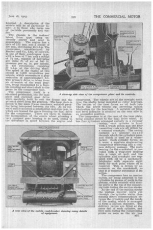
The compressor itself is a standard production, but the base plate and enclosed gear drive were specially built to suit the frame and the primary drive from the gearbox. The base plate is bolted to the main frame members, suitable packing being interposed between the two. At its forward end is mounted a substantial cast-ironcase, in which are housed the gears forming the final drive for the compressor. There are three in number, the interposition of the centre wheel allowing a very compact gear housing to be used, owing to the difference in speed between the engine and
A close.up compressor. The wheels are of the straight tooth type, the shafts being mounted on roller bearings. The bottom of the case forms an oil bath into which the lower wheels dip, providing splash lubrication for the bearings. A suitable oil filter, and level indicator is situated on the rear side in an accessible position. The compressor is at the rear of the base plate, being coupled direct to the final drive wheel. It has four cylinders arranged radially in a circular casing ; each cylinder is fitted with a trunk piston and the four connecting rods are all driven by a common crankpin. The casing contains a n annular space through which the cylinders pass, and which is used as a waterjacket. Each cylinder forms, as it were, a separate single-acting compressor delivering into a common delivery passage. The main bearing for the crankshaft is provided with a 'ring-oiler dipping Into a large oil well, and the cylinders and crankpin are supplied with oil by a mechanical lubricator with separate sight feeds for each point where oil is required. This is driven by an eccentric on the crankshaft, so that it is entirely automatic in its action.
The compressor has no suction valves, air being admitted to the cylinders by means of ports in the pistons, which coincide with similar ports in the top of the connecting rods during the suction stroke.
At the end of the suction stroke the pistons uncover ports cut through the cylinder walls, thus making direct communication between the cylinders and the inside of the casing, which is arranged to form a suction chamber. The delivery valves are fitted at the outer end of each cylinder, and they open during the compressing stroke as soon as the air has reached the required delivery pressure ; through them the air passes to the delivery passage, from which it passes through an automatic unloading device and pipe line to the container at the rear of the chassis. The automatic unloading device is bolted direct to the outlet of the compressor and is in the form of a by-pass opening the delivery to the atmosphere. It is automatically controlled by _an air relay connected to the reservoir, so that, when the pressure reaches the desired limit, the by-pass valve opens the delivery chamber to the atmosphere, thus removing the load from the engine. As soon as the pressure falls to a predetermined minimum this valve closes, and the compressor begins to deliver air again.
Silencing the Escaping Compressed Air.
The noise of the escaping air is reduced as much as possible, when this device comes into operation, by a silencer on the top of the vehicle. To prevent the racing of the engine which -.-:?sults when the load is removed a governor is fitted to the induction pipe, operated by air pressure. This consists of a spring-loaded plunger in a small cylinder, one end of which is connected by a smallbore copper pipe to the delivery passage of the compressor. A steel rod, screwed into the plunger, extends through the other end of the cylinder and is connected to a butterfly valve in the induction pipe.
The spring is adjusted to close at 98 lb. pressure per sq. in., and when the air in the delivery passage reaches this figure the plunger operates and closes the butterfly valve, reducing the speed of the engine, so that the compressor only delivers a small quantity of air. Directly the pressure falls below 98 lb. per sq. in the butterfly valve opens and the engine resumes its normal speed. This arrangement enables the machine to work eveialy without the unloading device coming into operation, although the latter acts as a safeguard should the former fail to operate. The cooling of the compressor is effected by a large radiator mounted on brackets above the gearcase, an air draught being induced by a fan eriven by a belt from the main shaft The pipes connecting the radiator and compressor are extended to the cooling system on the engine. By means of suitable cocks the two systems are brought together when the machine is at work, the pump on the engine delivering water round the entire circuit. This enables the machine to work over long periods without overheating.
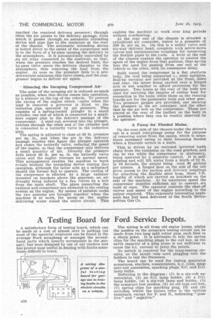
At the rear end of the chassis is situated a cylindrical air contaiffer, tested to a pressure of 200 lb. per sq. in. On this is a safety valve and six-way delivery head, complete with screw-down valves and instantaneous couplings for connecting the flexible pipes to the tools. A lever at the end of the chassis enables the operator to control the • speed of the engine from that position, thus saving him the need for passing from one end of the vehicle to the other, with its consequent delay.
Built round the compressor is a fiat platform body, the roof being supported c.i steel uprights. Roll-up curtains are provided at the front, sides and rear, the latter being carried over a hinged arm in wet weather to afford protection for the operator. Two boxes at the rear of the body are used for Carrying the lengths of rubber hose for connection to the tools, while those on the running boards are for the pneumatic tools and other gear. Two pressure gauges are provided, one showing the pressure in the air container, and the other that in the air belt on the compressor. These are placed at the rear of the toolbox on the body in a position where they can be readily observed by the operator.
A Pump for Flooded Mains.
On the near side of the chassis under the driver's cab is a small rote-plunge pump for the purpose of removing water from the mains, which is sometimes necessary owing to their becoming flooded when a fracture occurs in a main.
• This is driven by an enclosed inverted tooth chain from the extension on the road gearbox, and can be run while the compressor is stationary, being operated by a separate control. It is selfpriming and will lift water from a depth of 22 ft. in 16 seconds, the .output being „bout 30 gallons per minute. A hinged door on the side of the cab gives access to the suction and delivery couplings for attaching the flexible steel hose, three 7-ft. lengths of which are carried on brackets on the side of the machine. • At its maximum speed the compressor supplies sufficient air to operate, six tools at once. The operator controls the shut-off valves and speed of the engine according to the output required. This extremely interesting appliance has just been delivered to the South Metropolitan Gas Co.