


Patents Completed.
Page 20
If you've noticed an error in this article please click here to report it so we can fix it.
Complete specifications of the following patents will be sent to any address in the United Kingdom upon receipt of eightpence per copy at the Sales Branch, Patent Office, Holborn, W.C.
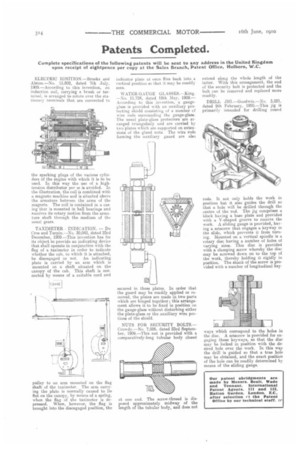
ELECTRIC IGNITION.—Brooks and Alston.—No. 15,802, dated 7th July, 1909.—According to this invention, an induction coil, carrying a brush or termilial, is arranged to rotate over the stationary terminals that are connected to
the sparking plugs of the various cylinders of the engine with which it is to be used. In this way the use of a hightension distributor per se is avoided. In the illustration, the coil is combined with a magneto machine and is situated above the armature between the arms of the magnets. The coil is contained in a casing that is mounted in ball bearings and receives its rotary motion from the armature shaft through the medium of the usual gears.
TAXIMETER INDICATION. — Du Cros and Turpin.—No. 30,042, dated 23rd December, 1909.—This invention has for its object to provide an indicating device that shall operate in conjunction with the flag of a taximeter in order to indicate whether the cab, to which it is attached, be disengaged or not. An indicating plate is carried by an arm which is mounted on a shaft situated on the canopy of the cab. This shaft is connected by means of a suitable cord and
pulley to an arm mounted on the flag shaft of the taximeter. The arm carrying the plate is normally caused to lie flat on the canopy, by means of a spring, when the flag of the taximeter is depressed. When, however, the flag is brought into the disengaged position, the
indicator plate at once flies back into a vertical position so that it may be readily seen.
WATER-GAUGE GLASSES.—King. —No. 11,724, dated 18th May, 1909.— According to this invention, a gaugeglass is provided with an auxiliary protecting shield consisting of a number cf wire rods surrounding the gauge-glass. The usual plate-glass protectors are arranged triangularly and are carried by two plates which are supported on extensions of the gland nuts. The wire rods forming the auxiliary guard are also secured in these plates. In order that the guard may be readily applied or removed, the plates are made in two parts which are hinged together; this arrangement allows it to be fixed in position on the gauge-glass without disturbing either the plate-glass or the auxiliary wire portions of the shield.
NUTS FOR SECURITY BOLTS.— Crowdy.—No. 7,026, dated 23rd September, 1909.—This nut is provided with a comparatively-long tubular body closed at one end. The screw-thread is disposed approximately midway of the length of the tubular body, and does not extend along the whole length of the latter. With this arrangement, the end of the security bolt is protected and the bolt can be removed and replaced more readily.
DRILL JIG.—Goodwin.—No. 3,221, dated 9th February, 1910.—This jig is primarily intended for drilling round rods. It not only holds the work in position but it also guides the drill so that a hole will be drilled through the centre of the rod. The jig comprises a block having a base plate and provided with a V-shaped groove to receive the work. A sliding gauge is provided, having a setscrew that engages a keyway in the slide, which prevents it from turning. Mounted on a vertical spindle is a rotary disc having a number of holes of varying sizes. This disc is provided with a clamping screw whereby the disc may be screwed down on to the top of the work, thereby holding it rigidly in position. The shank of the screw is provided with a number of longitudinal key.
ways which correspond to the holes in the disc. A setscrew is provided for engaging these keyways, so that the disc may be locked in position with the desired hole over the work. In this way the drill is guided so that a true hole may be obtained, and the exact position of the hole can be readily determined by means of the eliding gauge.