


New Crossley Trolleyblis
Page 31
If you've noticed an error in this article please click here to report it so we can fix it.
Uses Oder Components
Maintenance Simplified and Spares Stocks Reduced, in those Organizations Operating Oil engined Machines
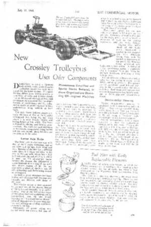
DESIGNED to carry a 56-seater body of 8-ft. width, a new Crossley trolleybus chassis has been introduced for the home market. The specification differs from former practice in a number of ways and follows closely that of the current oil-engined bus, with consequent opportunities for the simplification of maintenance and for reduction in stocks of spares required in those undertakings using vehicles of both types.
The main frame follows almost precisely the lines of that of the Crossley oil-engined bus, being Ili ins, deep where it is most heavily loaded and having flanges of 3-in. width. The frame is braced by channel and tubular crossmembers. No rivets are used anywhere in the chassis, components being bolted and the nuts locked. Body brackets are the same as in the oiler.
Lower Axle Ratio The front axle is also common with that of the Crossley motorbus, and so are tyres and springs, both front and rear. Because of the need for a different ratio, there is a slight variation in the case of the rear axle, which has a 9.33 to 1 reduction, instead of 6.5 to 1, which is usual on the oil-engined buses. Despite the change, the differential is accommodated in a casing of the same size. Worm centres of 8i ins, are employed in place of the 8-in, size, all related bearings and shafts being revised to correspond.
Air brakes, shock absorbers and hand brakes, with all cross-shaft bearings and linkages, are identical with those of the oiler.
The traction motor is now mounted to the near side of the chassis, instead of being located centrally, as in earlier models. Any of the well-known types of trolleybus electrical equipment can be incorporated, that on the model inspected by "The Commercial Motor" being of Metropolitan-Vickers manufacture and utilizing an air-duct ventilator; capacity is 105 h.p.
Previously, all power wiring was carried inside the chassis, but ease of access has now been improved by running it through a duct inside the body, where it can easily be examined by removing a metal cover. Transmission is by a short tubular shaft from the traction motor (which is Silenthloc mounted) to a coupling at the rear axle, with needle-roller universal joints at each end.
In passing, it may be mentioned that the only trouble experienced with trolleybuses in Manchester during thepast 12 years has been caused through salt thrown up from the road in winter. To eliminate this difficulty, terminal bars and connections have now been rearranged. Sliding of the transmission shaft, caused by axle movement, takes place in a splined sleeve at the forward end of the shaft, any slight end pressure being borne on a ball-thrust bearing in 'the casing of the motor, so as to relieve the armature of any load. A.cceleration figures for the new vehicle are given as 2.5 m.p.h. per sec. per see. Rheostatic control is provided on the brake pedal, so as to ensure a minimum of wear on the braking mechanism and the brake facings.
During t h e initial travel of the brake pedal, retardation is applied in two stages—
first t h e rheostatic
action, then, with the secondary depression of the pedal, the Westinghouse graduated a i r brake comes into action. A motor of I h.p. continuous rating is employed and is separated from the frame by dry-spot insulation, providing a long leakage path.
T'ne air reservoir is fitted with a safety valve and the system is tested up to 100 lb. per sq, in. pressure. Two gauges on the instrument panel indicate pressure in the reservoir and in the brake cylinders. Both hand and foot controls operate internal-expanding brakes working in 161-in.-diameter Chromidium drums.
Double-roller Steering
Marles double-roller steering is employed, with a steering-box ratio of 28 to I. Rear springs are underslung, whilst those at the front are mounted over the axle beam. Chassis lubrication is by oil, using a Tecalernit highpressure gun to suit hook-on nipples.
Overall measurements show a slight variation to meet the adjustments needed for the 8-ft. body. Track at the rear is now 6 ft. I in., and at the front 6 ft. 104 ins.; the wheelbase measures 16 ft. 71 ins., with an overall length of 25 ft. lat ins. Ground clearance is 10.1 ins., and the laden height of the frame 1 ft. IN ins. Turning circle is now 59 ft. Wheel sizes arc 10.50 by 20 singles at the front and 9.75 by 20 twins at the rear.