


Water Cooling for Injection Nozzles
Page 36
If you've noticed an error in this article please click here to report it so we can fix it.
A Resume of Patent Speccations That Have Recently Been Published
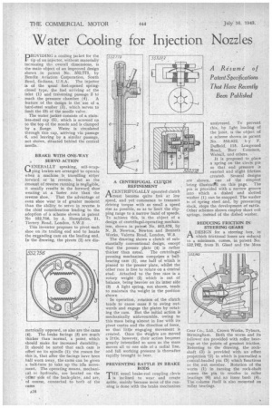
PROVIDING a cooling jacket for the tip of an injector, without materially , increasing the overall dimensions, is the main object of an improved design shown in patent No. 552773, by Bendix Aviation Corporation, South Bend, Indiana, U.S.A. The injector is of the usual fuel-opened springclosed type, the fuel arriving at the inlet (1) and traversing passage 2 .tt-5
reach the pressure chamber (4). A feature of the design is the use of a hard-steel washer (3), which serves to limit the lift of the needle valve.
The water jacket consists of a stainless-steel cap (5), which is screwed on to the top of the nozzle and is clamped by a flange. Water is circulated through this cap, arriving via passage 6, and leaving by a similar passage, not shown, situated behind the central needle.
BRAKE WITH ONE-WAY SERVO ACTION
GENERALLY speaking, self-wrapping brakes are arranged to operate when a machine is travelling eittier forward or in reverse, but as the mount of reverse running is negligible, it usually results in the forward shoe wearing at a faster rate than the reverse shoe. That the advantage of even shoe wear is of greater moment than the ability to servo in revetse is the chief consideration leading to the adoption of a scheme shown in patent No 552,758, by A. Humphries, 21, Tierney Road, London, S.W.2
This inventor proposes to pivot each shoe on its trailing end and to locate the expanding cam on the leading end. In the drawing, the pivots (2) are dia metrically opposed, as also are the cams (4). The brake facings (3) are much thicker than normal, a point, which should make for increased durability. It should be noted that each cam is offset on its spindle (1); the reason for this is, that after the facings have been half worn away, the cam i can he given a half-turn to take up the idle move. ment. The operating means, mechanical or hydraulic, are located on the 'othicr side of the back-plate, and are, of course, connected to both of the A CENTRIFUGAL CLUICH REFINEMENT
ACENTRIFUGALLY operated clutch must become quite free at low speed, and yet commence to transmit driving torque with as small a Speed rise as possible, so as to limit the slipping range to a narrow band of speeds. To achieve this, is. the object of a design of centrifugal-operating mechanism, shown in patent No. 552,578, by N. B. Newton, Newton and Bennett Works, Valetta Road, London, W.3.
The drawing shows a clutch of substantially conventional design, except that the presser plate (4) is rather thicker than usual. The centrifugal pressing mechanism comprises a 'ballbearing cam (1), one half of which is pinned to the• presser plate, whilst the other race is free to rotate on a central stud. Attached to the free race is a rotary weight (2) which is out of balance, being heavier on its inner side (3) A light spring, not shown, -tends to maintain the weight in the position shown • In operation, rotation of the clutch tends to cause mass 3 to swing outwards and engage the plates by rotating the cam. But the initial action is mechanically unfavourable, owing to this mass being almost in line with its pivot centre and the direction of force, so that little engaging movement is created. Once the vV'eights are moved a little, however, their action becomes greatly intensified so soon as the mass moves all to one side of a radial line, and full working pressure is thereafter rapidly brought to bear.
PREVENTING RATTLE IN BRAKE RODS
THE usual brake-rod coupling clevis is inclined to wear and create rattle, mainly because most of the running is done with the brake mechanism
unstressed. To prevent this, by light loading of the joint, is the object of a scheme shown in patent No. 353,022, by F. Duffield, 115, Longwood Road, 'Barr Common, Walsall, and others.
It is proposed to place a spring on the clevi:s pin so that end pressure is exerted and slight friction created. Several designs are shown, one of the simplest being illustrattd on this page. The pin is provided with a narrow groove into which a dished and slotted washer (1) can be snapped. The washer is of spring steel and, by preventing slack, stops the development of rattle. Other schemes shown employ short coil springs, instead of the dished washer.
REDUCING FRICTION IN STEERING GEARS
A DESIGN for a steering box, in Pt which frictional losses are reduced to a minimum, comes, in patent No. 552,762. from B. Gleecl and the Moss Gear Co., Ltd., Crown Works, Tyburn, Birmingham. Both the worm and its follower are provided with roller bearings at the points of greatest friction. Referring to the drawing, the rockshaft (3) is provided with an offset projection 12) in which is journalled a conical-headed pin (5) which functions as the nut member. Rotation of the worm (1) in turning the rock-shaft causes the pin to revolve in roller bearings (6) and an inner bush (4). The column itself is also mounted on roller bearings.