Welding Technique Applied to Body Construction
Page 32

If you've noticed an error in this article please click here to report it so we can fix it.
How it is Possible to Obtain Additional Torsional Rigidity Without Extra Cost or Weight Increase
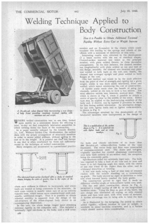
WHERE welded construction was, at one .time, looked VV upon merely as a convenient means for effecting' a ioint, to-day we find completely fabricated assemblies in which welding forms the basis of the construction. In a paper recently released by the Lincoln Electric Co., Ltd., Welwyn Garden City, Hertfordshire, the author deals with the proper anangenu.nt of structural members in order to secure added stiffness, without aading to the cost or to the weight. It is pointed out that" this feature is one that is often overlooked by those not sufficiently versed in the technique of welded construction, Many designers are accustomed to conventional practice where such stiffness is difficult to incorporate, and where loads are treated as being concentric, to the structure. In such cases torsion is usually taken care of as an entirely separate issue, which means extra•constructional work and, usually, additional weight. That it is possible to obtain inherent stability is apparent from the design of the sub-structure of the refuse-disposal body shown in an ,accompanying illustration.
In this case, the whole design hinged upon obtaining torsional rigidity in the composite unit. This included a torsionally rigid sub-frame in the body,and a stiff cross member and an X-member in the chassis which could translate this loading to the .springs and wheels of the vAhicle with a minimum of distortion or side sway.
Interesting results were obtained in the development of a beam section with the use of standard shapes. Channel-section material was taken as the principal member, with plate welded thereto, in three successive arrangements. In the first instance, the channel member ran longitudinally with plate welded at toe and heel of one flange; secondly, the channel was inverted and plate was welded to both heels at the web. and, finally, the channel was arranged upright and plate welded to both flanges at the toes.
This last method was found to be the most effective from the point of viewof strengtkand rigidity for a given weight, whilst it was more easily fabricated, fitted and • welded, which meant minimizing the cost of construction.
A further study made clear the benefit of using two channels, welded at the toes to folm a box section. The most effective section was, however, evolved later. This, • which is shown in Fig. 1, made it possible to obtain a . centre of gravity close to the middle of the beam. Either type may be applied to the load-carrying members of the body and, if desired, can be tapered if provision be made. for this during welded fabrication. An alternative design, for use with lighter loads and as lighter cross-members, is shown in Fig. 2.
The advantages obtained by this development of the fabricated members were incorporated, in the design of the body and chassis sub-frame of no fewer than 300 24-cubic-yd. refuse-collection bodies of the type illustrated. The entire body and floor were constructed of corrosion-resistant steel. The doors and tail-gate, originally specified for riveted aluminium construction, were later built entirely of arc-welded steel, the exception being the removable parts.
Specifications called for extremely rigid tests. The body was required to take a load of six tons and to raise and lower it to full clumping angle five times, with the centre of one rear wheel 12 ins, higher than the other, and to withstand distortion or twisting.
A test was made using a load of nine tons of steamed cinders, with the vehicle standing on a considerable up-grade. The body showed no signs of distortion or twist and when lowered barely touched the body guides.
The construction proved so rigid that it made no difference whether.single or twin-cylinder hoists were used.
The bar and plate _construction, shown in Fig. .1, permitted 'a weight saving of 120 lb. in the longitudinal members alone. Using the floor as part of the beam, the new design also eliminated all coping, as only sheared plates and bars were used, with little waste. of material. A further advantage was in being able to bend the bars cold.
As is illustrated by the foregoing, the abilitji to obtain added rigidity, without increase in cost or weight, is available in many machine structures, and is a feature which should receive more consideration.


