


BRITAIN BUILDS SPEED DBILE ARMY INTRUDER
Page 26
Page 27
Page 28
If you've noticed an error in this article please click here to report it so we can fix it.
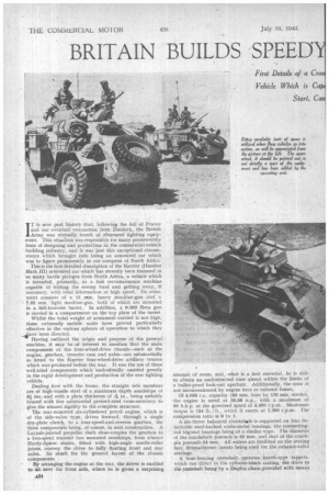
IT is now past history that, following the fall of France and our eventual evacuation from Dunkirk, the British Army was virtually bereft of atmoured fighting equipment. This situation was responsible for many praiseworthy feats of designing and production in the commercial-vehicle building industry, and it was just this exceptional circumstance which brought into being an armoured car which was to figure prominently in our conquest of North Africa.
This is the first detailed description of the Karrier (Humber Mark III) armoured car which has recently been featured in so many battle pictufes from North Africa, a vehicle which is intended, primarily, as a fast reconnaissance machine capable of hitting the enemy hard and getting away, if necessary, with vital information at high speed. Its armament consists of a 15 ram. heavy machine-gun and a
' 7.92 mm. light machine-gun, both of which are mounted in a full-traverse turret. In addition, a 0.303 Bren gun is carried in a compartment on the top plate of the turret.
Whilst the total weight of armament carried is not high, these extremely mobile units have proved particularly effective in the various spheres of operation to which they kave been directed. .
Having outlined the origin and purpose of the present machine, it may be of interest to mention that the main components of the four-wheel-drive chassis—such ai the engine, gearbox, transfer case and axles—are substantially as fitted to the Karrier four-wheel-drive artillery tractor which was produced before the war. It was the use of these well-tried components whichundoubtedly assisted greatly in the rapid development and production of the new fighting vehicle.
Dealing first with the frame, the straight side members are of high-tensile steel of a maximum depth amidships of tli ins, and with a plate thickness of A in., being suitably braced with five substantial pressed-steel cross-members to give the utmost rigidity to the complete structure.
The rear-mounted six-cylindered petrol engine, which is of the side-valve type, drives forward, through a single dry-plate clutch, to a four-speed-and-reverse gearbox, the three components being, of course, in unit construction. A Layrub-jointed propeller shaft close-couples the gearbox to a two-speed transfer box mounted amidships, from whence Hardy-Spicer shafts, fitted with high-angle needle-roller joints, convey the drive to fully floating front and rear axles. So much for the general layout of the chassis components.
By arranging the engine at the rear, the driver is enabled to tit over the front axle, where he is given a surprising amount of room, and, what is a first essential, he is able to obtain an unobstructed view ahead within the limits of a bullet-proof look-out aperture. Additionally, the crew is not inconvenienced by engine heat or exhaust fumes.
Of 4,085 c.c. capacity (8.5 mm, bore by 120 min. stroke), the engine is rated at 26.88 tip., with a maximum of 90 b.h.p. at the governed speed of 3,400 r.p.m.. Maximum torque is 184 lb./ft., which it exerts at 1,300 r.p.m. The compression ratio is 6 to 1.
A six-throw balanced crankshaft is supported on four detachable steel-backed white-metal hearings, the connectingrod big-end bearings being of a similar type. The diameter of the crankshaft journals is 65 mm. and that of the crankpin journals 54 EOM . • All valves are Stellited on the seating face, Brimachrome inserts being used for the exhaust-valve
seatings. .
A four-bearing camshaft operates barrel-type tappets, which run direct in the cylinder-hlock casting, the drive to the canisliaft being by a Duplex chain.provieled with means
for adjustment The generous diameter of the gudgeon pins provides for a small-end bearing of large area, and this is lubricated under pressure via a drilling in the connectingrod web. A gear-type pump, accessibly mounted on the manifold side of the engine an driven off the camshaft by skew gears, in tandem with the ignition distributor, is responsible for oil circulation.
Considerable attention has been devoted to the lubrication system, and the circuit includes a floating filter in the sump, and a by-pass filter and a full-flow instrument, so that all reasonable precautions have been taken tb ensure
clean oil in the crankcase. There is an oil cooler arranged behind the engine radiator, the by-pass control to and from which is arranged for manual operation. 4The sump capacity is 21 pints.
Engine cooling is entirely dependentupon the efficiency of the fan, which is six-bladed and 20-in. diameter. Special cowling runs forward from the radiator to encompass the fan, which induces its air supply from points above and below the engine compartment, and expels it, via the radiator, through louvres at the rear of the body. The dual belts which drive the fan also form the drive for the water pump and dynamo, the former being of the centrifugal-impeller type.
Engine temperature is thermostatically controlled, the system running at a pressure of about 5 lb. per sq. in., according to the setting of he pressure-loading valve, which is incorporated in the thermostat housing.
Mixture is fed to the engine by a Solex down-draught carburetter, which is provided with a governor operating on the velocity principle. The cam-operated petrol pump draws its supply from tanks carried in the engine compartment, the total fuel capacity being 30 gallons-25 gallons in the main tank and live gallons reserve. This quantity of fuel gives the vehicle a radius of action of about 250 miles.
A C.A.V. 12-volt, compensated-output dynamo looks after the supply of electricity, the battery equipment consisting of two 6-volt 110-amp.-hr. batteries, wired in series. The system is adequately screened throughout, as, of course, the machine carries wireless equipment.
A point of interest in connection with the Borg and Beck clutch -and gearbox mounting lies in the disposing of the gearbox on its side, in order to provide a flat floor to the fighting compartment. Unorthodox as this may appear, the arrangement has proved itself in, service. The box provides four forward Speeds, top and third being constantmesh gears, and second and first of the sliding-pinion type. In conjunction with the two-ratio transfer box, eight forward and two reverse ratios are available, giving a range from 8.69 to 1 to 86.5 to 1, with an axle ratio of 6.86 to I.
The transfer box is driven from the gearbok by a short shaft provided with Layrub universal joints: the box being ' three-point-mounted on Silentbloc large-capacity bearings. Wide-face, double-helical gear:are employed on the higher ratio, and straight-tooth gears for the emergency low ratio.
Under certain conditions it is urdesirable to retain the
drive on both axles, and provision is made for engaging or disengaging the drive to the front axle through the medium of a dog clutch. Controls for the gearbox and transfer box are carried forward to the driving compartment, the gearbox control being on the left and the two transfer-box controls on the right of the driver.
Hardy-Spicer open-type shafts, with needle-roller-bearing universal couplings, take the respective drives to the front and rear 'axles, both of which are.fully floating units. In keeping with the other main components, the axle casings are exceptionally sturdy, that at the front being a one-piece banjo-type steel casing and that at the rear a welded pressed-steel component.
The front axle carries a flange at each end, to which is bolted the spherical steel casings -enclosing the universal joints, which are of the Tracta constant-velocity type. The drive to the flanges bolted to the road-wheel hubs is through tubular stub axles, which are carried on taper-roller bear-ings. The centres of the stub axles coincide with the universal-joint centres, -and thus, in effect, fo'rm the steering pivot. Cam-and-roller steering gear is used, a transverse shaft running from the centrally disposed steering box to• the drop arm. A four-pin bevel differential gear, with straddle-mounted pinion, and final drivg by spiral bevel, are common to both axles.
Although the Suspension is oi orthodox design, in that semi-elliptic springs are enaployed, I'se use of trunnion ends and blocks provides for a movement of about 15 degrees in each direction, thus providing considerable relief to the back plates and spring-anchorage points. Piston-type shock absorbers,. vertically mounted, are used at the front and rear, and this suspension system, in conjunction with 10.50-in. by 20-in. lpw-pressure "run-flat" tyres, gives to the vehicle a cross-country performance of a high standard. Lockheed hydrauiically operated Cowdrey braking is
employed, the cast Millemte drums being 16 ins, in diameter and providing for a 3-in.-wide area of contact. The hand lever controls brakes on only the rear wheels, the pedal, by direct mechanical means, controlling the brakes on all four wheels.
Heat-treated, nickel-chrome,., molybdenum high-tensile ,BP. plate, is used for the bod), or hull, as it is called, all joints being effected by welding. It is four-point flexibly mounted on the chassis and is pi avided with additional stabilizers at the corners to prevent excessive-relative movement between it and the chassis. •
As previously mentioned, the gun turret provides for a 360-degree traverse and is constructed to carry three men, the traversing operation being carried out manually.
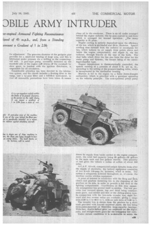
To conclude this description, it may oe of interest to quote one or two leading dimensions and weight and performance figures. The total all-up weight of the complete vehicle is approximately" 7 tons. It has a wheelbase of 8 ft. 61 ins, and a track sof 6 ft. 4 ins, at the front and 6 ft. at the rear. The lowest point of the axles provides for a 1-ft. ground clearance. The vehicle has a maximum speed of 45 m.p.h. and can surmount a maximum gradient, from a standing start, of 1 in 2.06. As is well known, Karrier Motors, Ltd., is amongst the country's leading commercial-vehicle manufacturers, and its efforts at the present time are typically representative of the Magnificent contribution which is being made to the war effort by the industry as a whole. There is no doubt that the production of suchqmorthodox types of vehicle as that described, for operation under conditions of the greatest severity, cannot but be of inestimable value in the creation and development of post-war road vehicles. Thus, the civilian operator may hope eventually to reap the benefits of the experience gained by this maker in the production of machines specifically designed and built to smash the enemy.