


Further Development of the ROBERTSON VARIABLE GEAR
Page 74
If you've noticed an error in this article please click here to report it so we can fix it.
AGEAR which attracted considerable attention some time back, and which was known as the Robertson Variable Gear, was described in• this journal at the time it was introduced. The present invention is a development of the original idea (patent No 306,752), in which
a cone is slidably carried on the driving shaft of the engine and contacts with a ring of frictional material mounted on a disc attached to the driven shaft.
To obtain a low relative Speed of the driven' shaft the ring is brought into contact with a •relatively small part of the cone, whilst to obtain top gear the -ring is brought into axial alignment with the engine shaft, thus causing it to act as a common cone clutch and driving the driven shaft at the same speedas the engine shaft. All intermediate speeds are obtained by placing the, ring so that it makes contact at different parts of the cone. By this means an infinitely variable gear is obtained.
The present invention relates to a means for automatically regulating the position of the ring in relation to the cone. For this purpose the torque reaction of the sleeve of the propeller shaft is employed. It is obvious that the greater the resistance to movement, midi as when climbing a hill, the more the bevel pinion is inclined to climb up the crown gear as it drives the vehicle. Advantage is taken of this inclination to move the position of the disc carrying the ring to a part of th;
cone which is of smaller diameter, and thus reduce the gear ' ratio automatically.
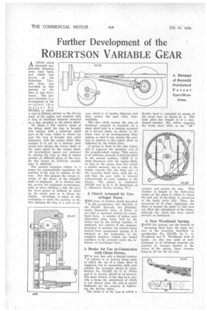
The disc which carries the ring of frictional material is mounted on a short shaft held in a bearing mounted on a pivoted shaft, as shown in the lower view of an accompanying illustration, so that it can assume the position in relation to .the engine shaft as indicated by the dotted lines.
A spring is fixed to the side frame, and it supports the foremost end of the propeller-shaft casing. This spring is of sufficient strength to hold the shaft in the normal position, which is in axial alignment with the engine shaft, so long as the torque does not exceed a certain amount; but so soon as the torque exceeds this the front end of the propeller shaft rises, with the result that the gear ratio is lowered automatically in exact relation to the torque. The patent is numbered 313,303 and is by j. H. Robertson, of 1, Albemarle Street, London, W.1.
A Clutch Actuated by Centrifugal Force.
TFM form of friction clutch described
in the specification (No. 301,013) of the Societe Nouvelle des Etablissemeats Decauville Mae, of Paris, is one that is operated entirely by centrifugal force. A number of plates, each alternative plate being held by the driven and by the driving member, is employed, but instead of the pressure necessary to produce the friction being derived from compressed springs it is obtained by the inclination of the weighted members (which are linked together) to fly outward under the influence of centrifugal force.
A Brake for Use in-Connection with Chain Drives.
IT is true that only a limited number of vehicles is at present being metre in which the use of a chain drive is employed, but in connection with such vehicles the invention shown in specification No. 313,287. by C. G. Pullin and S. L. Groom, should be of interest. The main feature of the idea is to provide a brake the adjustment of which is not altered when the axle is moved backward for the purpose of tightening the driving chain.
The brake is of the type in which a flexible band is expanded by means of the usual cam, as shown at A. The back plate has hinged to it a starshaped member (B), which supports the brake hand when in the " off" Position and carries the cam. Thrs member is hinged to the back-plate proper at the point C, which is where the pull rod of the brake is connected to the brake lever (D). Thus, the movement of B when tightening the chain is around the point C; this does not affect the adjustment of the brake, although the wheel has been moved forward or backward.
A New. Woodhead Spring.
DADS for springs and the method of
mounting them farm the main feature of the invention described in, specification No. 313,181, by G. A: Woodhead and F. Woodhead, both of Leeds. In this case pads of antifrictional or of frictional material are inserted in recesses formed in the leaves of the spring, these recesses being in all but the top leaf.