MODERNIZING an
Page 58

Page 59

Page 60

If you've noticed an error in this article please click here to report it so we can fix it.
If-date Goods Vehicle
"FIROGRESS in the design of the commercial vehicle has been extraordinarily rapid during the past few years, with the result that the modern machine is unquestionably very efficient. It follows, therefore, that all operators whose finances permit the use of modern vehicles are well advised to purchase them, because the faults of the earlier types have now been eliminated and an overall improverlent in efficiency has caused operating costs to be reduced accordingly.
In these days of fierce competition, however, it is obvious that there must be many owners who do not feel justified in speculating to the extent of purchasing new vehicles. Although they realize the benefits which accrue from the acquisition of a modern fleet, they shrink from taking the step on account of the expense involved. It is intended in this article to indicate to this type of operator how, when overhauling ber.omes necessary, a number of alterations to the design of both the power unit and transmission may result in an overall improvement in efficiency and performance at a cost which should not be prohibitive.
Before an attempt is made even to desctibe how a chassis may be " hotted-up " it must be explained that all the components in the make-up of a vehicle are more or less co-ordinated to each other, so that if one item be altered and its efficiency -improved it is more than likely that it will affect several other components.
The Modern Vehicle Has a High-speed Engine.
We can now deal with the chassis in general. The modifications which are to be outlined are especially suited to vehicles with a loading capacity of three tons and over, especially if they be fitted with large-diameter solid tyres. One of the essential differences between the modern vehicle andone, say, five years old is that the engine of the former normally runs at higher speeds, which in effect means that the 1-0fir• axle reduction must have a higher ratio, or, in other words, a lower gear.
Now, when a vehicle is due for a general overhaul there are many components which must be replaced. In the engine, for instance, Pistons and rings become worn, valves are often badly pitted and the seatings in the cylinders may require recutting. Again, the camshaft and certain parts of the tappet gear, being highly stressed units, are subject to wear, and as these parts have to be replaced, it seems fairly dear that for a slightly increased expenditure the design of the parts in question may well be altered if beneficial results accrue from so doing.
Factors Limiting Revolutions are Co-related.
Now it must be realized from the start that in order to improve the power output of an internal-combustion engine the only convenient method to adopt is to raise the peak of the power curve. In other words, the engine must be capable of " revving " faster. There are, of course, two limiting factors to revolution • speed, one being connected with the thermal side—i.e., gas velocity, turbulence, rate of burning, etc.—whilst the other concerns the inertia of the moving parts. Fortunately, the two • characteristics are interconnected and the modifications demanded by the thermal side are also necessary from the mechanical point of view.
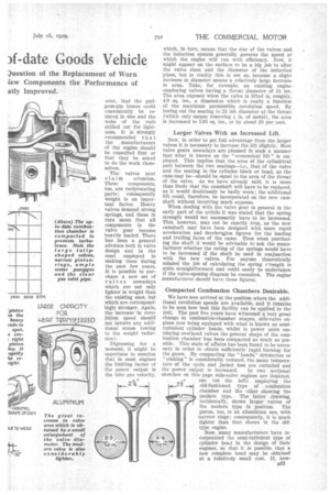
Let us refer to the power curves reproduced in these pages. The first curve (A) shows the power capabilities of the engine in its existing form. The second curve (B) indicates what can be done by suitable "betting-up." It will be seen that the "peak" revolution speeds are increased from 2,200 r.p.m. to 2,600 r.p.m., the curve rising meanwhile so that the maximum power is increased by something in the order of 20 per cent. The lower ends of the two curves are purposely shown with a slight advantage to the modified engine. This 1332 characteristic is the result of thermo
dynamic Improvements, details of which are given later.
We can now turn to a consideration of details. In the first place there is little doubt but that the Pistons and connecting gods — in other words, the reciprocating parts of the engine—will undoubtedly be somewhat bulky and heavy, so that the first consideration should be one involving a general reduction in the weight of these parts. Aluminium pistons, for instance, are available at quite moderate prices. If the cylinders require boring out new pistons will• have to be purchased in any case; this modification, therefore, costs nothing extra.
T 11 e connecting rods are, of course, a different matter. Here care must be taken that strength is not sacrificed by the reduction of weight, for, although the inertia stresses generally will he lower at the ordinary rates ot revolution speed, the fact that it is hoped to increase the speed during the process of overhauling makes the stress remain at a more or less constant figure. It is just possible, how ever, that the gudgeon-pin bosses could conveniently be reduced in size and the webs of the rods drilled out for lightness. It is strongly recommended that • the manufacturers of the engine should be consulted first or that they be asked to do the work themselves.
The valves next claim attention.
These components, too, are reciprocating parts; consequently
weight is an important factor. Heavy valves demand strong springs, and these in turn mean that all components in the valve gear become heavily loaded. There has been a general advance both in valve design and in the steel employed in making them during the past few years. It is possible to purchase a new set of valves nowadays which are not only lighter in weight than the existing ones, but which are correspondingly stronger. Again, the increase-in revolution speed should not involve any additional stress (owing to the weight reduction).
Digressing for a moment, it might be opportune to mention that in most engines the limiting factor of The power output is the inlet gas velocity,
which, in turn, means that the size of the valves and the induction system generally governs the speed at which the engine will tun with efficiency. Now, it might appear on the. surface to be a big job to alter the valve sizes and the diameter of the induction pipes, but in reality this is not so, because a slight increase in diameter means a relatively large increase In area. Take, for example, an existing engine employing valves having a throat diameter of 24 ins. The area exposed when the valve is lifted is, roughly, 4.9 sq. ins., a dimension which is really a function of the maximum permissible revolution speed. By boring out the seating to 2i in. diameter at the throat (which only means removing 4 in. of metal), the area is increased to 5.95 sq. ins., or by about 20 per cent.
Larger Valves With an Increased Lift.
Now, in order to get full advantage from the larger valves it is necessary to increase the lift slightly. Most valve gears nowadays are planned fn such a manner that what is known as the "economical lift" is employed. This implies that the area of the cylindrical part between the two seathags—i.e., that of the valve and the seating in the cylinder block or head, as the case may be—should be equal to the area of the throat of the valve. As we have already said, it is more than likely that the camshaft will have to be replaced, as it would doubtlessly be badly wont ;,the additional lift could, therefore, be incorporated on the new cam shaft without incurring much expense.
When dealing with the valve gear in general in the early part of the article it was stated that the spring strength would not necessarily have to be increased. This, however, may not be exactly true, as the new camshaft may have been designed with more rapid acceleration and deceleration figures for the leading and trailing faces of the cams. Thus when purchasing the shaft it would be advisable to ask the manufacturer whether the rating of the springs would have to be increased if the shaft be used in conjunction with the new valves. For anyone theoretically minded the job of calculating the spring OTength is quite straightforward and could easily he undertaken if the valve-opening diagram be consulted. The engine manufacturer should have these figures.
Compacted Combustion Chambers Desirable.
We have now arrived at the position where the additional revolution speeds are available, and it remains to be seen how best this facility can be applied. to the unit. The past five years have witnessed a very great change n combustion-chamber shapes, side-valve engines now being equipped with what is known as semi• turbulent cylinder heads, whilst in power units employing overhead valves the general shape of the combustion chamber has been compacted as much as possible. This state of affairs has been found to be necessary in order to obtain sufficiently rapid burning for the gases. By compacting the " heads, ' detonation or "pinking" is considerably reduced, the mean temperature of the cycle and jacket loss are curtailed and the power output is increased. In two sectional sketches on this page side-valve engines are depicted. one (on the left) employing the old-fashioned type of combustion chamber and the other showing the modern type. The latter drawing, incidentally, shows larger valves of the modern type in position. The piston, too, is an aluminium one, with narrow rings ; consequently, it is much lighter than that shown in the oldtype engine.
I •
2
Now, many manufacturers have incorporated the semi-turbulent type of cylinder head in the design of their engines, so that it is possible that a• new complete head may be obtained at a relatively small cost. If, how
ever, this be not practicable, it may be possible to compact the combustion chamber by raising the crown of the piston until it practically fits the top of the cylinder head. This alteration will raise the compression ratio at the same time and cause the power output throughout the whole speed range to be increased accordingly. Again it will be advisable to consult the makers of the engine, as the exact amount of the increase of the compression ratio must be so calculated as to avoid any possibility of incurring subsequent trouble due to an excessive pressure.
This article will be concluded in The Commercial Motor and we shall explain how the various auxiliaries can be modified and tuned up to suit the altered power unit, whilst the rest or the chassis will be dealt with in detail in simple and straightforward language. The modifications are not intended to be really extensive; they are given entirely with the intention of advising the operator to scrap worn parts only, and instead of replacing the components with new ones of the same type, the improved performance can be obtained by altering slightly the design of the parts concernetl, (To be concluded.)


