


London s Electric Taxicabs.
Page 4
Page 5

If you've noticed an error in this article please click here to report it so we can fix it.
We referred, in our last issue, to the electric taxicabwhich has been prf.)duced by The Electromobile Company, 1_1:Tilted, of 7, Hertford Street, Mayfair, W., and Greenwood nod Batley, Limited, of Leeds, for the Electric Taxicab Company, Limited, of London, whose prospectus was issued last week. Following our announcement, a member of the Editorial staff of COMMERCIAL MOTOR visited the Electromobile Company's depot and made a complete examination of one of these new machines, our present description of which will be read with interest by all students of the London motorcah question.
The design of the electric taxicab keeps closely to the lines of the wellknown " Elecrromobile " landaulets, which have been so successfully employed for private hiring in the West End of London. There have been, however, several important modifications, in order to make the vehicles more suitable for public-service work, and to meet the requirements of the Metropolitan Police. regulations.
The whole of the parts are conveniently arranged on a pressed-steel frame, which is mounted over the axle,
at the forward end by two semi-elliptic springs 36 inches long, and at the back end by three similar springs, the two side ones of which are 42 inches long.
The battery of 45 E.P.S. cells is contained in a single box, which is slung from the under-side of the frame in a very ingenious manner, and this permits of the rapid changing of the complete battery. The wooden box is strongly braced by a light-steel framework, and this is terminated at each of tile four tcp corners in a stout lug; screw-operated, tapered pins are caused quickly to engage in holes in the four lugs, and these pins may be actuated from either side of the vehicle by means of a box-spanner brace. in the depot, the box is lowered from its position under the chassis • by means of a
hydraulic lift, and in this way it can be taken down and transferred to the charging room very promptly. The total weight of a battery and box complete is about if cwt., and the capacity is 135 ampere-hours, which is sufficient fcr an average run of 45 miles.
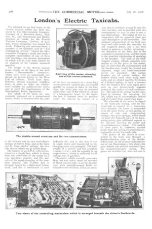
The motor, which normally generates Sh.p but can safely stand an overload of about TOO per cent,, is of the hi-polar type, with specially-wound fields, arranged in two sections ; it has an arma ture that is similarly wound in two distinct sections, and is .provided with two commutators as may be seen in one oi our illustrations. The object of this arrangement will be apparent from our later description of the controller. The compact arrangement of the field castings and coils avoids the necessity for any magnetic joints, and it has been found to possess a further advantage : the distortion of the field, due to the armature is counteracted, and the result is the practical elimination of sparking at the brushes, The shell of the fieldmagnet casting affords complete protection to all the parts of the motor, but, in order that the commutators and the brushes may readily be cleaned and adjusted, large and easily-removable covers are provided. The carbon brushes are of special design; the holders which carry them hang vertically, and are drawn together by means of a helical spring, in such a manner that the brushes bear with equal pressure on two diametrically opposite points of the surface of each commutator. The pull of the spring can be regulated by turning the adjusting nut (13), which nut is automatically locked and prevented from slackening back.
The after-side of the motor is clipped to the back-axle casing, and its forward side is secured to a transverse steel channel ; the latter is suspended from the main frame, at two points, by means of rods and compensating springs ; two plate springs, which stand' out from the forward sides of the backspring palms, give additional support to. the channel carrying the motor and transmission-gear casing. The weight of these parts is, therefore, carried' partly from the spring-mounted chassis, and partly on the live hack axle.
The power of the motor is transmitted to the back axle through a. double-reduction gear, of the doublehelical type, in the manner indicated by one of our illustrations ; this shows the gear wheels and pinions removed from the transmission-gear easing. Thegears are machine cut, and each one is made up of two pieces securely bolted together. The silent running of the Electromobile vehicles may partly be attributed to the employment oi finelycut, double-helical gearing.
The differential shafts are relieved of all but torsional strains ; their outer ends are squared, and engage in square holes in the driving-wheel hubs ; the axial loads are carried on the external tubes which constitute the axle casing. Hoffmann ball bearings are employed for the axle and wheels, as, indeed, they are throughout the whole of the transmission system.
The system of control, whilst permitting all the cells of the battery to remain in series at all times, provides for six rates of speed in a forward direction and one reverse speed, and the whole of the controlling mechanism is assembled under the driver's footboards.
The arrangements of the electric circuits for each of the controller positions are shown by the accompanying diagram. Figure i shows the grouping for the two lowest forward speeds, and it will be seen that the two windings of the armature, and both the sections of the field windings, are connected together in series with the battery and a resistance (R). The onlv difference between speeds Nos. i an..l 2 lies in the amount of resistance (R) which is introduced in the circuit ; this resistance, by the way, is only employed for the two starting speeds, for reversing, and when the electric brake is brought into operation. Figure 2 shows the circuit for the third speed. and it is the same as Figure , so far as the armature (A) and the field (F) are concerned, but the resistance has been cut out of the circuit. For the fourth speed (Figure 3), the armature windings remain in series, but the field windings are arranged in parallel. For the fifth speed (Figure 4), the armature windings are in parallel and the fields are in series, and, for the sixth speed (Figure 5), both the armature and the field windings are separately arranged in
but the armature remains in series with the field.
When the electric brake is brought into action, the arrangement of the armature and . field windings is the same as for the sixth speed forward, but the battery is cut out-of the circuit,
and the latter is closed through .a sistance (R) that is sufficient to reduce the speed of the vehicle(which is now driving the motor as a dynamo) to about three miles an hem.; Figure 6' shows the brake circuit. The control lever is mounted below the steering wheel, and it actuates the controller spindle through bevel pinions. There is a notched wheel (H), on the end of the spindle, with which a spring-loaded roller is caused to 'engage, and this prevents any possibility of the controller's sticking midway between any two contact positions. At the other end of the controller spindle, another small .wheel is mounted, and this is provided with a single notch ; a roller, fitted to the lower ,end of the lever (J),, can be pulled into this notch, by means of a helical spring, and, when in that position, the upper end of the lever. (J.) is clear of the safety plug hole (K.), and permits of the insertion of the plug which completes the main circuit. This operation can only be carried out when the controller is in the neutral position ; it is, consequently, impossible to cause any damage such as might occur were the plug to be placed in, or withdrawn from., the hole while the circuit was closed through the controller. The resistance frame (M) is situated to the left of the controller (L). .
The, single pedal (G) does duty for quickly breaking the circuit, and for applying the back-wheel brakes. The first portion of the pedal's movement causes a boxwood quadrant (D) to rotate, so that one of the two brushes which bear on its surface is no longer in contact with the metal-covered portion, and is, consequently, insulated by the boxwood ; the current is, therefore, compelled to traverse through a magnetic cut-out, which is connected as a shunt across the two brushes to which we have referred. The further movement of the pedal separates two carbon contacts (C), between which the final break in the circuit is made, and also applies the wheel brakes. As the
pedal is depressed, a small ratchet quadrant (shown in the bottom lefthand corner of the illustration at the foot of the preceding page is also caused to rotate, and, when the spindle (E) is pushed down with the left foot, its lower end engages with the teeth of the ratchet quadrant and locks the latter in any desired position ; instantly the pedal (G) is given a slight push, the spindle (E) is set free, and the circuit will be completed, and the brakes released, as the pedal rises to its normal position. This inter-locking gear has been found useful for traffic stops.
The wheel brakes are provided with renewable shoes, and these are brought into operation by the action of cams in quite the usual manner. The cam spindles are, however, mounted in floating bushes which are bored eccentrically to their external diameter ; the object of this arrangement is to ensure that each of the brake shoes shall bear on the faces of the drums with equal pressure. The cams can, by reason of the eccentric bushes, take up positions to suit the inequalities in the fitting or wearing of the shoes. The arrangement is illustrated, by a diagram, which, however, is not to scale and does not show the exact proportions of the various parts. Another sketch shows the ingenious adjustment and compensating lever which is used for these brakes. The side-lever brake acts within a small drum on the secondmotion shaft, and is also provided with an easy means of adjustment.