


Patents Completed.
Page 24
If you've noticed an error in this article please click here to report it so we can fix it.
TUBE CLEANERS.—Kitchen.—No. 6,814, dated 27th March, 1908.—This apparatus consists of a casing (3) having a
spiral guide-way (2) for the receptien of a chain (1). The end of the chain extends through a nozzle (8) arranged in the top of the casing (3); this nozzle is tapered at one end and screw-threaded at the other. A nut (9i, terminating in a spike, is screwed on the screw-threaded portion. A sprocket wheel (4) carried by a spindle (5) engages the chain (1) in the -.ozzle (8). This sprocket wheel is adapted o be actuated by a handle (7) on the spindle (5). The nozzle (8) is adapted to enter the tube to be cleaned, and the adjustable nut is screwed so that the spike engages the wall of the steam, or water, [rum. The handle (7) is then turned, bus forcing the chain (1) through the tube to be cleaned.
SPARKING PLUG.—Ransford.—No. 143, dated 2nd January, 1908.—In order that the plug may be readily taken to
pieces for the purpose of repairing, the Central conductor (a) is provided with a boss (b) which is adapted to fit in the sleeve (c1) containing, a packing ring (1). The sleeve (el) is itself contained within' an insulating member (a), whilst the whole is arranged within an outer casing (f) and securely held in .position by a nut (k) which forces the various members against the washers, or packing rings j, h, so as to make air-tight joints. SPARKING PEUG.—Fox and Another. —No. 19,190, dated 26th August, 1907.— A central conductor (A), which is provided with a spade-like head (a) at one end, and is screw-threaded at the other, is held in the insulating block (B) by the nuts (b, h1). The outer casing (C) is in the form of a stuffing box, and packing rings (115) are provided which are compressed by the nut (0) which bears on the insulating block (b). The lower end of the casing (c) is formed with an internal flange (c3) extending to within a short distance of the head (a) of the central conductor so that, formed between the latter and the internal flange are tv.c) short spark gaps.
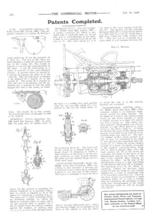
CONVERTED HANSOM.—Reid.—No. 23,108, dated 15th November, 1987.—According to this invention a hansom cab is converted into a motorcab by attaching a motor to the fore part of the former. The engine is arranged to drive the front
wheels through differential gear ; whilst the steering column (6) is arranged at the hack of the vehicle so that the driver can steer in the usual manner from the seat (E). The steering rod (B1) carrying the hand wheel (D) is connected by means of a ball joint to a rod (F) which has _a ball joint connection with another rod (0). This last rod is connected to a, screw shaft (h) and operates the lever (K) to which the rods (1) of the steering brackets are connected.
TRANSMISSION SYSTEM.—HallNo. 13,911, dated 17th June, 1907.—This invention relates to an improved' transmission system for -motor vehicles. The fly wheel (a) is hollow and contains a disc clutch (hi, the driven member of which is rigidly secured to a shaft (b4) extending into a caring (c). This casing contains epicyclic change-speed, and reverse, gearing, tlt rough which motion is transmitted to the driven shaft (e). A device for locking the parts of the change-speed gearing is provided in the form of an expanding band type clutch (f). The driving member of this clutch consists of a pair of arms (f1) connected to the shaft (c) and carrying the expanding band elements (/)2, 13) ; whilst the driven element consists of a drum (ft) rigidly connected to the rearmost speed-controlling drum (p0) in such a manner that, when the band sections (t-2, f3) of the clutch are expanded, the whole of -the parts of the change-speed gearing are locked so that they rotate together, thus forming an auxiliary fly wheel. At the rear of the change-speed casing (c) a disc type brake (in operated by the lever (he) is arranged. The operating levers (hi, he), which, respectively, control the disc-type main clutch (b) and the brake (h), are coupled together by a series of connecting rods (1, 11) and a bell crank lever (is). This link and lever system is connected -to a single operating pedal (13) in such a manner that, by continuing the movement of the pedal after disengagement of the clutch, the disc-type brake (It) will be brought into action.