


PATENTS SUMMARIZED.
Page 22
If you've noticed an error in this article please click here to report it so we can fix it.
Paterson's Carburetter.
Mr. Paterson's carburetter_ was described some time ago in this journal. It may be recalled that the, particular feature of Mr. Paterson's invention Was that the temperature of the incoming mixture is arranged to be increased in inverse proportion to the throttle opening, so that with a small opening, and the engine, as a rule, running slowly and therefore, perhaps, inclined to be cooler than usual, a greater amountfof heat is • imparted, with a consequent tendency to keep the mixture comPletely gaseous th ruukhout.
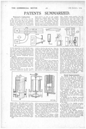
This end is attained by interconnecting with the thruttk a baffle, which operates, when the throttle is nearly closed, to divert the gases so that they have to traverse a special superheating chamber; with the throttle open, on the other hand, they are short-circuited and pass direct from the preliminary heater to the induction pipe. The carburetter is, in view of this somewhat complicated process, quite a
simple affair. The main body is cylindrical, and is surrounded by a easing of such,a size that there is an annular space all round the carburetter This outer casing is divided, the upper portion scaled as regards. the outereatmosphere, while the lower serves -as a. means of entrance for the air for the mixture. Reference should he made to the drawing which we reproduce. There are three choke tubes, with corresponding jets. Exhaust gases enter by the 'lower right
C50 hand branch as seen on our central illustration, -impinge upon. the. smalleet of the three choke tubes, and being baffled by a central division, pass upwards outside the innermos, cylindrical part of the carburetter. Tney pass through apertures in the baffle plate near the topof the cylinder, then travel &len wards on the far side and out. Both on entering and on leaving they are brought into close contact with the other two choke tubes. It will be realized that these gases impart considerable heat both to the wall of the innermost cylinder, and to the exterior wall of the casting, which wall, again, is gurrounded by. the annular fleece to which we have already drawn. attention.
Witlijn the inside of the cylinder fits a block of refractory material, which is pierced with a number of holes Passing through from the bottom to the top. The branch pips at the top of the carburetter, and to the right, passes to the engine induction manifold. The throttle, with which is eombined the special bypass device, is a portion of a cylinder
which passes across the inner en-d of this pipe. krom thaeserond illustration it will be seen that depending from the.throttle valve is a narrow passage shaped in the form O1. a segmenueof a circle Also attached to the throttle valve iS'a. ported disc, which uncovers in turn, .until all three are exposed, the three choke ttibes and their respective jets.
The operation is as fames :—With the throttle valve 'practically closed, only the smallest choke tube is in opera tion. Under engine suction, hot air, which is drawn round the outside of the exhaust-heated box and enters the choke tube from below, -round the jet, is sucked into the carburetter, richly endowed with fuel. This-mixture is drawn up the many holes in the cylinder of refractory material, and—we are present ing the'engine has been warn ed up—is there still further heated. Reaching the top of this cylinder, direct entrance into the induction manifold is found to be blocked, and the gases are then compelled to pass through the whole length of the snperheatrig chamber, which is that narrow passage between the outermost casing and that in .which the ex• lauet gases circulate, until it reaches the bottom of this segmental passage -up which it travels, and then reaches the engine. As the throttle valve is opened further, the second jet comes into play, and a proportion of the mixture is allowed to reach the throttle valve direct. Finally, all three jets, with their choke tubes, are exposed, and the gas panes direct from. the -top innermoet
cylinder to the induction pipe. The specification number is 120,739.
Detail Improvements.
No. 120,780, S. E. Alley, describes a method of suspending an engine in spherical bearings, attached to the side frames of the chassis. Accessibility appears to be the main object. The same patentee, in No. 120,781, shows a construction of front axle wherein the usual forging or stamping carries only one bearing for each of the pivot pins. The outer is carried. on a separate forging bolted to the. main one.
No. 120,873, the Fiat Co., show a construction of engine with sheet metal jackets whereby the induction manifolds are carried through a hot water jacket from one side of the engine to the other.
3. Easlam, in No. 120,754, constructs the male portion of a cone clutch from stampings, but in two parts, with the plate conneeted to the rim at the centre of the latter.
A. J. Hill, in No. 120'762, describes an electric alarm for advising the driver that the supply of lubricant is low.
The Parkinson meter for sepplying gas to flexible gas holders on motor vehicles is described in No. 1208..Q4
J. Joiner, in No. 120,778, patents a method of applying' supplementary wheels to tractors. -The wheel is carried on an eccentric on the main wheel boss, so-that it can be swnng into--contact with the road, or out of it, as required.