The Spring Suspension of Six-wheelers
Page 68

If you've noticed an error in this article please click here to report it so we can fix it.
A .1R6sum of Recently Published Patent Specifications
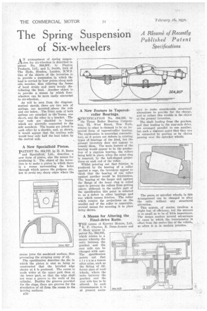
AN arrangement of spring suspension for six-wheelers is described in Patent No. 364,907. by Flexion Products, Ltd., and L. Smith, both of The Hyde, Hendon, London, N.W.9. One of the 'objects of the invention is to provide a suspension in 'which the load is carried by four points along each side member, thus relieving the frame of local strain and more evenly distributing the load. Another object is to provide a means by which fourwheelers can be more easily converted to six-wheelers.
As will be seen from the diagrammatical sketch, there are two sets of springs, one mounted above the axle and one below. The front ends of both springs are attached to tfie'frame, one direct, and the other to a bracket. The rear ends are shackled to beams which are pivotally connected to the side members. The beams are joined to each other by a shackle, and, as shown, it would appear that the trailing axle would bear only half the load taken by the central axle.
A New Specialloid Piston.
PATENT No. 364,787, by H. N. Bates and Speeialloid, Ltd., describes a new form of piston, also the means for producing it. The object of the invention is to make a piston in which there is a recess surrounding the holes through which passes the gudgeon pin, but to avoid any sharp edges where the recess joins the machined surface, thus preventing the scraping away of oil.
The specification describes the die in which the piston is cast as being so constructed that the bevelled edge shown at 4 is produced. The recess is made wider at the upper part than at the lower part, so that the edge shall not wear a groove in the walls of the cylinder. Besides the grooves provided for the rings, there are grooves for the circulation of oil from the recess 0 the bearing surfaces.
B50
A New Feature in Tapered, roller Bearings.
SPECIFICATION No. 304,860, by the Tyson Roller Bearing Corporation, 75, West Street, New York, relates to what is claimed to be an improved form of tapered-roller bearing. The explanation is somewhat contradictory, as it points out defects in existing types of bearings of the kind, but the present invention' does net appear to remedy them. The main feature of the bearing would appear to be the production of a cageless bearing, the rollers being held in place, when the outer ring is removed, by the ball-shaped projections on each end of the roller.
Whilst pointing out that friction is produced by the bearing of a roller against a cage, the inventors appear to think that the bearing of one roller against another would be frictionless. The bearing of the larger end against the flange of the inner ring is relied upon to prevent the rollers from getting askew, although in the earlier part of the specification this point is referred to as a defect in other bearings and one which causes friction. The collar which retains the projections on the smaller end of the roller is removable, several means for securing it in place being shown.
A Means for Altering the Final-drive Ratio.
THE names of Barrier Motors, Ltd., R. F. Clayton, R. Dean-Averns and P. Meek appear in Patent No. 364,803, which relates to a means whereby the ratio between the gearbox and the rear axle can be changed with ease. The specification points out that circumstances often arise, such as the fitting of different sizes of road wheels, where the ratio between the gearbox and the rear axle has to be altered. In such circumstances it is at present neces sary to make considerable structural alterations to provide for the change, and to reduce this trouble is the object of the present invention.
The shaft leading from the gearbox, and that leading to the rear-axle drive. are arranged parallel to one another. but such a distance apart that they can be connected by gearing or by chains passing over the sprocket wheels.
The gears, or sprocket wheels, in this arrangement can be changed to alter the ratio without any structural alteration.
This system, of course, involves a slight loss of efficiency, hut the amount is so small as to be of little importance. The design confers several advantages in cases in which the transmission is offset from the eentre line of the vehicle, as often it is in modern practice.


