


A CATALYTIC IGNITION DEVICE.
Page 32
If you've noticed an error in this article please click here to report it so we can fix it.
A Résumé of Recently Published Patent Specifications.
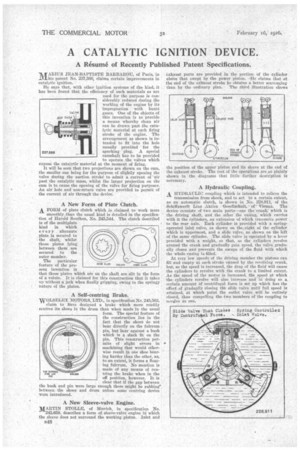
'AA-ARIUS JEAN-BAPTISTE BARBAROU, of Paris,' in itihis patent No. 237,566, claims certain improvements in catalytic ignition.
He says that, with other ignition systems of the kind, it has been found that the efficiency of such materials as are used for the purpose is considerably reduced during the working of the engine by its impregnation with burnt gases. One of the objects of this invention is to provide a means whereby clean air can be drawn past the catalytic material at each firing stroke of the engine. The arrangement as shown is intended to fit into the hole usually provided for the sparking plug. A special camshaft has to be provided to operate the valves which expose the catalytic material at the moment of firing.
It will be seen that two projections are shown on the cam, the smaller one being for the purpose of slightly opening the valve during the suction stroke to admit a current of • air past the catalytic mass, whilst the larger projection on the cam is to cause the opening of the valve for firing purposes. An air hole and non-return valve are provided to permit of the current of air througlt the device.
A New Form of Plate clutch.
A FORM of plate clutch which is claimed to work more smoothly than the usual kind is detailed in the specification of Harold Southall, No. 245,544. The clutch described is of the multiplate
kind in which ever y alternate plate is secured to the shaft, whilst those plates lying between them are secured to the outer member.
. The particular feature of the present invention is that those plates which are on the shaft are slit in the form of a volute. It is claimed for this construction that it takes up without a jerk when finally gripping, owing to the Springy nature of the plates.
A Self-centring Brake.
WOLSELEY MOTORS, LTD., in specification No. 245,563, claim to have designed a brake which more readily centres its shoes in the drum than when made in the usual form. The special feature of the construction lies in the fact that the shoes do not bear directly on the fulcrum pin, but bear against a bush which is a slack fit on the Din. This construction permits of slight errors in machining that would otherwise result in one shoe bearing harder than the other, as, to an extent, it forms a floating fulcrum. No mention is made of any means of centring the brake when in the off position, however. It is clear that if the gap between the bush and pin were large enough there might be rubbing' between the shoes and drum unless some centring device were introduced.
A New Sleeve-valve Engine.
MARTIN STOLLE, of Munich, in specification No. 245,658, describes a form of sleeve-valve engine in which the sleeve does not surround the working piston. Inlet and B48 exhaust ports are provided in the portion of the cylinder above that swept by the power piston. -He claims that at the end of the exhaust stroke be obtains a better scavenging than by the ordinary plan. The third illustration shows the position of the upper piston and its sleeve at the end of the exhaust stroke. The rest of the operations are so plainly shown in the diagrams that little further description is necessary.
A Hydraulic Coupling. • A HYDRAULIC coupling which is intended to relieve the transmission from shock, and to act, to a certain extent, as an automatic clutch, is shown in No. 2'28,911, of the Schiffswerft Linz Aktien GeseilAchaft, • of' Vienna. The device consists of two main parts—one the crank.which is the driving shaft, aud. the other the casing,' which carries with it the cylinders, an extension of which transmits power to the rear axle. . Each cylinder is provided with a springoperated inlet valve, as shown on theiright of the cylinder which is uppermost, and a slide valve, as shown on the left of the .same cylinder. The slide valve ig operated by .a lever provided with a weight, so that, as the cylinders revolve around the crank and gradually gain speed, the valve gradually closes and prevents the escape of the fluid with which the whole casing is filled.
At very low speeds of the driving member the pistons can fill and empty at each stroke caused by the revolving crank, but, as the speed is increased, the drag of the fluid will cause the cylinders to revolve with the crank to a limited extent. As the speed of the motor is increased, the speed at which the cylinders revolve will also increase and in doing so a certain amount of centrifugal force is set .up which has the effect ,of gradually closing the slide valve until full speed is attained, at which point the outlet valve will be entirely closed, thus compelling the two members of the coupling to revolve as one.