


THE BEST WAY TO HANDL ANT PNEUMATIC TYRES.
Page 16

Page 17
Page 18
If you've noticed an error in this article please click here to report it so we can fix it.
Some Practical Hints on the Removal eplacement of Giant Straight-sided, by an Expert. Tyres as Demom
MYRE-CHANGING is one of those jobs 'which give no trouble at all to the expert, but which are apt to prove lengthy and laborious to anyone not especially
• skilled at the work. Particularly is this the case in dealing with giant pneumatics of the extremely large sizes which are becoming so popular for motor coaches. It therefore seems opportune to devote a little attention to the best methods for removing and, replacing the stigaight-sided giant pneumatic which is at present so widely used.
The tyre is fitted to a rim which hasea fixed flange at one edge, the opposite edge being depressed all the way round to form a lip or groove. A loose flange at this opposite edge of the rim is lOcked in place by a spring ring which fits into the groove in the rim of the wheel. The edges of the cover are, of course, of the wired inextensible type, so that when the loose flange is locked it is quite impossible for the tyre to come off, even if it should become totally deflated.
For the Man who has to Remove and Replace a Tyre.
Any vehicle operator who has been using these tyres for a considerable time without experiencing any kind of trouble will probably have forgotten just how they were fitted to the wheels, so that when he gets his first puncture he may be rather at a loss to know how bestto deal with the job of removing the cover.
We will, therefore, first deal with this aspect of the matter, our remarks being based on a special demonstration which was given to us by an expert fitter at the Dunlop Co.'s London service depot. The tyre in question was a 1,085 mm. by 185 mm. giant pneumatic, Inflated to about 90 lb. per square inch, although the precise pressure depends upon the load.
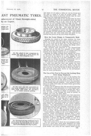
After jacking up the axle, undoing the nuts and sliding the wheel off the studs, deflation is the first operation, and this is simply a matter of using the cap of the Schrader valve to unscrew the valve insert and remove it. When the air has been exhausted the wheel should he placed flat on the ground, with the locking ring upwards.
Before describing the next step we may mention that two levers are supplied for handling these tyres, which are shown in one of the sketches reproduced, and are numbered 1 and -2 for reference, No. 2 having a special Y-shaped end.
A Useful Pair of Levers.
Returning to the tyre, the bent end of lever No. 1 is placed between the ends of the locking ring and the lever is then used to press the loose flange downwards; the thin end of lever No. 2 is then used to force the stepped end of the locking ring out of the groove in the wheel. Having got the end out, it is a simple matter to work the rest of the ring out of .the groove a little at a _time. The loose flange can then be lifted off.
In order to remove the cover the wheel should now be turned over on to a small block of wood so that the fixed flange comes uppermost, the cover then being free to drop clear lithe valve is of the latest swan-neck pattern, which is ingeniously fitted to a slot in the wheel.
However, if the valve is of the older type, which projects through a hole cut in the wheel rim, it must be pushed back from the inside through the hole before the cover will drop off. The cover being off, it is a simple matter to take out the tube for repair, and,. of course, before replacing it, -care should be taken to examine the cover and remove the puncturing object, Which may still be embedded.
The replacement of the cover is naturally not quite so easy as its removal, there being several details requiring a little care. No attempt should be made to replace the tube in the cover without first exhausting practically all the air from the tube, because, otherwise, it will be difficult to get it in.
The position of the tube in the cover is immaterial, B,32 and when it is in place a little air can be forced into the tube to cause it to take its proper shape. The circular flap which is provided should then be carefully fitted all round and smoothed out.
The wheel is next laid on the ground with the fixed flange downwards, when the assembled cover and tube can be dropped over it if the valve is of the latest pattern, the valve simply falling through the slot. In the case of the older type of valve, the cover should first be worked round until the valve is exactly in line with the hole in the rim. The valve can then be pushed back to enable the cover to fall over the rim, and, if the alignment is correct, the valve will spring out through the hole without any trouble. Care should be taken that the valve stem does not catch in the locking-ring groove as the tyre drops into place.
How the Loose Flange is ..Temporarily Held.
Keeping the wheel in the same position, the loose flange is dropped into place and is forced down at a point next to the valve by using the thin end of lever No, 2; the thick end of lever No. 1 is then inserted in the groove and can be left holding the flange downwards when lever No. 2 is withdrawn.
The operator then proceeds to the diametrically opposite side of the rim (i.e., opposite to the valve) and uses the thin end of lever No. 2 to press down the portion of the flange which is not yet in position.
.Keeping the flange pressed down against the thrust of the cover, the square end of the locking ring can be inserted in the groove at a point opposite to the valve, and, iflever No. 2 is then released, the cover will spring up, lifting the flange automatically and retaining the end of the locking ring in position.
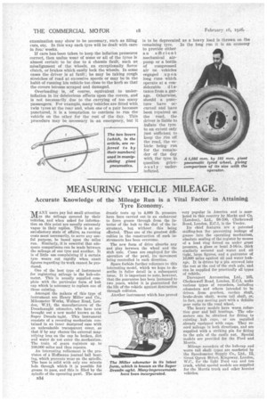
The operator then proceeds in a clockwise direction to a point just past the valve and pushes the loose flange downwards with one lever, while he uses the other to get the locking ring into the groove. He should place his foot on the ring to hold it there, the whole of the operation being better shown by the photographs than by many paragraphs.
The Use of the Foot to Prevent the Locking Ring from being Displaced.
Having made sure that the half of the locking ring which has been dealt with is right home in the groove, and keeping his foot on the wheel to hold the ring in place, the operator can proceed to lever the remainder of the locking ring into position. Care should he taken that it is really well home all round before proceeding to inflate the tyre.
It must not be inferred that this process of removing and replacing a giant pneumatic is a very lengthy matter, because with a little practice it should only take a few minutes. Attention to detail is necessary, however, in order to get through the work as quickly as pOssible and with the least effort.
It seems appropriate to mention here that punctures do not often trouble the owners of fleets running on giant pneumatics. In fact, this type of tyre is found to stand up remarkably well. However, itstlife depends to a great degree upon the care taken by the operator, a . very important point which cannot too often be emphasized being the maintenance of the correct inflation pressure. The right pressure to use imust, of eourse,"be ascertained from the tyre company concerned,as it depends upon the size and type of the cover and the load which ithas to carry. The maximum load should be used as a basis. We give the figures on another page.
Under-inflation results in the cover being flexed excessively, whilst over-inflation imposes such a great tension upon the cord material that it is rendered abnormally liable to damage from concussion. Gauges attached to pumps are seldom reliable, so that it is better to apply a reputable make of pressure gauge direct to the tyre valve.
The hest method is to check the tyre pressures daily, and it is a good plan, when large distances are being covered by the vehicles in question, to remove one of the tyres weekly and carry out any repairs which careful B33 examination may show to be necessary, such as filling cuts, etc. In this way each tyre will be dealt with once in fou: weeks.
If care has been taken to keep the inflation pressures correct, then undue wear of some or all of the tyres is almost certain to be due to a chassis fault, such as misalignment of the wheels, an exceptionally fierce clutch, or brakes which easily lock the wheels. In some cases the driver is at fault ; he may be taking rough stretches of road at excessive speeds or may be in the habit of running his vehicle too close to the kerb so that the covers become scraped and damaged.
Overloading is, of course, equivalent to underinflation in its deleterious effects upon the covers, and is not necessarily due to the carrying of too many passengers. For example, many vehicles are fitted with twin tyres at the rear and, when one of a pair becomes punctured, it is a temptation to continue to run the vehicle on the other for the rest of the day. This procedure may be necessary in an emergency, but it
is to be deprecated as a heavy load is thrown on the
siderable d stance from a garage. Otherwise, should a puncture have occurred and have been repaired on the road, the driver is liable to inflate the tyre to an extent only just sufficient to keep the rim off the road, the vehicle being run for the remainder of the day with the tyre ip question grievously underinflated.