


Lubricating, Fuel Pumps.
Page 80
If you've noticed an error in this article please click here to report it so we can fix it.
/-1 A FUEL injection -pump having a lubricating oil, pump inebrporated inthe actuating link for a' diaphragm type of feed pump is the subject of patent No. 850,556 (C.A.V., Ltd., Warple Way, London, W.3).
In the drawing (1) FS the camshaft of the injection pump. This carries the eccentric which operates, via a central thrust rod, a fuel-feed pump shown generally at (2)." This is of the usual type, employing aspring-loaded flexible diaphragm (3).
The thrust rod is the chief novelty; it has two different diameters (4 and 5) both of which project into a common chamber (6). As the rod reciprocates it varies the effective volume of the chamber, and a pair of ball-valves convert the action into one of pumping. Oil is drawn in through a connection (7) and is discharged upwards via a bore (8) into the camshaft chamber. A return pipe is provided to take away any excess oil.
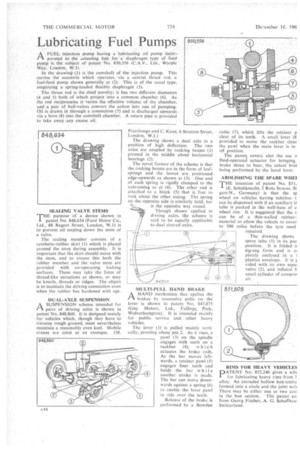
SEALING VALVE STEMS
THEpurpose of a device shown in patent No. 848,634 (Ford Motor Co., Ltd., 88 Regent -Street, London, W.1) is to prevent oil seeping down the stem of a valve.
The sealing member consists of a synthetic-rubber skirt (1) which is placed around the stem during assembly. It is important that the skirt should move with the stem, and to ensure this both the rubber member and the valve stem are provided with co-operating locking surfaces. These may take the form of thread-like serrations as shown, or may be knurls, threads or ridges. The object is to maintain the driving connection even when the rubber has hardened with age.
DUAL-AXLE SUSPENSION SUSPENSION scheme intended for pairs of driving axles is shown in patent No. 848,860. It is designed mainly for vehicles which, though they have to traverse rough ground, must nevertheless maintain a reasonably even keel. Mobile cranes are cited as an example. (M. Pratolongoand C. Kean, 6 Stratton Street, -London, W.1.) The drawing shows a dual axle in a position of high deflection. The two axles are coupled by rocking beams (I) pivoted in the middle about horizontal bearings (2).
The novel feature of the scheme is that the rocking beams are in the form of leafsprings and the leaves are positioned edge-upwards as shown at (3), One end of each spring is rigidly clamped to the axle-casing as at (4). The other end is attached to a block (5) that is free to rock about the other casing. The spring on the opposite side is similarly held. but is the opposite way round.
Though shown applied to driving axles, the scheme is said to be equally applicable to dual steered axles.
MULTI-PULL HAND BRAKE
rtA HAND mechanism that applies the brakes by successive pulls on the lever is shown in patent No. 847,875 (Guy Motors, Ltd., Fallings, Park, Wolverhampton). It is intended mainly for public service and other heavy
vehicles.
The lever (I)" is pulled mainly vertically, pivoting about pin. 2. As it rises, a pawl (3) on the spindle engages with teeth on a rackbar '(4), which actuates the brake rods. As the bar moves leftwards, a retainer pawl (5) engages finer teeth and holds the bar while another stroke is made. The bar can move downwards against a spring (6) to enable the lever pawl to ride over the teeth. Release of the brake is performed by a BoWden
cable (7), which lifts the retainer p clear of its teeth. A small lever (8 provided to move the rack bar clear the pawl when the main lever is in off position. _ The patent covers also the use fluid-operated actuator for bringing brake shoes to bear, the actual brat being performed by the hand lever.
ABOLISHING THE SPARE WHE1 THE intention of patent No. 851, -A(E. Schuhknecht, 3 Rote Strasse, St gart-N., Germany) is that the sp wheel on vehicles having tubeless t: can be dispensed with if an auxiliary ir tube is packed in the well-base of e wheel rim. It is suggested that the t can he of a thin-walled rubbermaterial to allow the vehicle to cover to 500 miles before the tyre need
(2) repaired. The drawing shows spare tube (1) in its pac position. It is folded it zig-zag form and is a pletely enclosed in a I plastics envelope. It is I vided with its own sepal valve (2), and inflated h small cylinder of compre! air.
RIMS FOR HEAVY VEHICLES
PATENT No. 852,246 gives a sell( for fabricating heavy rims from I alloy. An extruded hollow box-s.xtio formed into a circle and the joint welt There may be either one or two env' in the box section. The patent co from Georg Fischer, A. G. Schaffhau Switzerland.