


A Four-shoe Hydraulic Brake
Page 60
If you've noticed an error in this article please click here to report it so we can fix it.
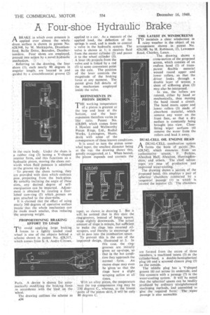
ABRAKE in which even pressure is applied over almost the . whole drum. surface is shown in patent No. 628,948, by M. Meiklejohn, Drumlamford, Bailie Drive, Bearsden, Dumbar. tonShire. Four shoes are, employed, PreSsed into action by a:novel hydraulic
mechanism. • Referring to. the drawing, the four shoes (1), each nearly 90 degrees in angular length, are located in and guided by a circumferential groove (2)
in the main body.. Under the shoes is a rubber ring (3) having a V-shaped interior form, and this functions as a hydraulic piston, moving the shoes outwards when fluid pressure is admitted
tcythe groove via pipe 4. .
• To -prevent the shoes turning, they are provided with slots which-embrace pins', projecting from the back-plate. By suitably inclining the angle of these slots,, any desired. degree of selfenergization. can be imparted. Adjustment is obtained by rotating a fourlobed cam-ring (5) which ,presses on pins attached to the shoe-webs: .
It is claimed that the effect of using nearly 360 degrees of operative surface Means that the whole mechanism can be made much smaller, thus 'reducing the unsprung weight.
.PROPORTIONING BRAKING . EFFORT TO LOAD
TO avoid applying large braking 1 forces to a lightly loaded rbad wheel is one. of the . objects. behind a scheme shown in patent No. 628,317, which. comes from S. A. Andre Citroen, Paris. A device is shown for automatically modifying the braking force in accordance with the load on the wheel.
The drawing outlines the scheme as A34
applied to a car. As a measure of the applied load, the deflection of the springs is used, and is made to control a valve in the hydraulic system. The valve is shown at 1; it receives fluid from the master cylinder (2) and passes it to the wheel cylinder (3). A lever (4) projects from the valve and is linked by a rod (5) to some convenient point on theaxle. The position of the lever controls the magnitude of the braking force at any m.oment. The patent gives full details of the mechanism employed inside the valve.
REFINEMENTS IN PISTON DESIGN
THE working temperature of a piston is greatest at the top and least at the bottom, and the heatexpansion therefore varies in like ratio. Patent No. 628,049, which comes from J. Howlett and Wellworthy Piston Rings, Ltd., Radial Wor deal
s, Lymington, Hants, with same of the C011 quences of these known conditions.
It is usual to turn the piston some t wha taper, the smallest diameter being at the top; the drawing showsthis, grealy exaggerated, at 1. When heated, 1
the piston expands and corrects the.
taper, as shown in drawing 2. But it will be noticed that in this state the ring-grooves, instead of being square, slope slightly downwards. The actual amount of slope is minute, but sufficient to make the rings into reversed oilscrapers, and thereby to encourage the oil to pass into the combustion space.
To prevent this is the aim of the imp! oved design, illustrated at 3.In this case, the ringgrooves are initially given an up-slope, so that in the hot condition they, approach the normal form. _ An excess slope may even be given so that the rings have a slight scraping action at all times.
With an alloy piston, the temperature near the top compression ring may be 230 degrees C., whereas, at the lowest 'point of the piston-skirt, it win be only 80 degrees C.
THE LATEST IN WINDSCREENS
TO maintain a clear windscreen in rainy weather is the object of an arrangement shown in patent No. 626,580, by H. Robinson, 13, Lawrence Road, Chorley, Lancs.
The drawing shows a cross-section of the proposed screen, which consists of an endless band (1) of transparent flexible material wound round upper and lower rollers, so that the driver looks through a double layer of screen; a sheet of stiffening glass (2) may also be interposed.
In use, the rollers are rotated, either by hand or mechanically, thus moving the band round a circuit. The band meets upper and lower rollers -(3) made of absorbent material, which remove any water on the front faiceo so that a dry surface is constantly being brought into view. Closefitting wiper surfaces (4) remove the water from the rollers ,and lead it away,
DUAL-CELL OIL ENGINE HEAD
ADUAL-CELL, combustion system forms the basis of patent „No. 628,542, which emanates from an authonitative 'source , F. Perkins, AlWalton 'Hall; Alwaltion, Huntingdonshire,' and .others. 'The 'chief advantages are ease of production and improved water cooling The drawing ihaws ,section of the proposed hcad; this employs a'pair of sphericalchambers connected , by a tangential passage (1)' in which is located_ the injector (2). -The chambers are formed from the onion of three 'members, a machined recess (3) in the cylinder-head, a double-hemispherical p1ug-(4) and a screwed closure plug (5) on -the outside.
The middle plug has a V-shaped groove (6) cut across its underside, and this connects with a passage (7) in the water-cooling system. It will be noted that the spherieal spaces cart be readily produced by ordinary straightforward machining methods, and assembled to 'give' the required form.' The water passage is also accessible