


A New Fuel-injection System
Page 62
If you've noticed an error in this article please click here to report it so we can fix it.
A Resume of Patent Specifications That Have Recently Been Published
A BATCH of live patents, Nos. PI 494,951/2/3/4/6, comes from the Attwood Diesel Equipment Co., Ltd., Great Westminster House, London, S.W.1, and others, disclosing a comprehensive injection system with many novel features, including improvements in fuel-lifting pumps, control methods, governing arrangements, and. injection nozzles.
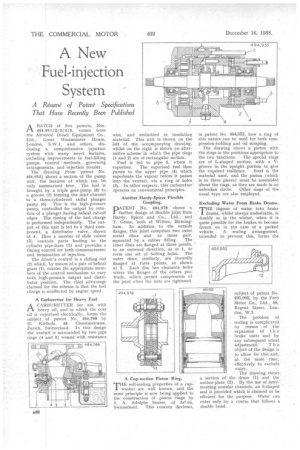
The drawing (from patent No. 494,955) shows a section of the pump unit, the features of which can be only summarized here., The fuel is brought by a triple gear-pump (8) to a groove (7) forming the inlet channel to a three-cylindered radial plunger pump (6). This is the high-pressure pump, controlled for output by rotation of a plunger having helical cut-oil edges. The timing of the fuel charge is performed independently. The output of this unit is led to a third component, a distributor valve, shown at 4. Here a number of slide valves (5) controls parts leading to the cylinder pipe-lines (3) and provides a timing control for both commencement and, termination of injection.
The driver's control is a sliding rod (2) which, by means of a pair of helical gears (1), rotates the appropriate members of the control mechanism to vary both high-pressure output and distributor position. The chief advantage claimed for the scheme is that the fuel charge is unaffected by engine speed.
A Carburetter for Heavy Fuel
ACARBURETTER for use with heavy oil, and in which the cold oil is vaporized electrically, forms the subject of patent No. 494,788 by II. Kielholz, 48, Clausiusstrasse, Zurich, Switzerland. In this design the venting is surrounded by two pipe rings (4 and 5) wound with resistance wire, and embedded in insulating material. This unit is shown on the left 'of the accompanying drawing, whilst on the right is shown an alternative scheme in which the pipe rings (1 and 2) are of rectangular section.
Fuel is fed to pipe 5, where it vaporizes. The vaporized fuel then passes to the upper pipe (4) which superheats the vapour before it passes into the venturi, via a ring of holes (3). In other respects, this carburetter operates on conventional principles.
Another Hardy-Spicer Flexible Coupling.
PATENT No. 494,978 shows a further design of flexible joint from Hardy, Spicer and Co., Ltd., and T. Green, both of Witton, Birmingham. In addition to the outside flanges, this joint comprises two outer metal discs and an inner pair, separated by a rubber filling. The inner discs are flanged at three points, in an outward direction, as at 1, to form one set of bolting holes. The outer discs, similarly, are inwardly flanged at three points, as shown at 2. Each disc has clearance holes where the flanges of the others protrude, which permit compression of the joint when the nuts are tightened.
A Cup-section Piston Ring.
THE self-sealing properties of a cupwasher are well known, and the same principle is now being applied to the construction of piston rings by S. A. Adolphe Saurer, of Arl;on,
Switzerland. This concern discloses, in patent No. 494,552, how a ring of this nature can be used for both compression-holding and oil scraping.
The drawing shows a piston with the rings in the positions appropriate to the two functions. The special rings are of L-shaped section, with a Vgroove in the upright portion to give the required resilience. Steel is the material used, and the piston (which is in three pieces) must be assembled about the rings, as they are made in an unbroken circle. Other rings of the usual type are also employed.
Excluding Water From Brake Drums.
THE ingress of water into brake drums, whilst always undesirable, is doubly so in the winter, when it is quite possible for the brakes to become frozen on in the case of a parked vehicle. A sealing arrangement, intended to prevent this, forms the
subject of patent No. 495,002, by the Ford Motor Co., Ltd., 88, Regent Street, London, W.1.
The problem of sealing is complicated by reason of the expansion of t h e brake units and by any subsequent wheel adjustment. T h e object of the design is • to allow for this and, at the same time, effectively to exClude water.
The drawing shows a section of the drum (1) and the anchor-plate (2). By the use of inter; meshing annular channels. an S-shaped seal is provided which is claimed to be efficient for the purpose. Water can enter only by a course that follows a double bend.