 1
1 2
2 3
3 4
4 5
5 6
6 7
7 8
8 9
9 10
10 11
11 12
12 13
13 14
14 15
15 16
16 17
17 18
18 19
19 20
20 21
21 22
22 23
23 24
24 25
25 26
26 27
27 28
28 29
29 30
30 31
31 32
32 33
33 34
34 35
35 36
36 37
37 38
38 39
39 40
40 41
41 42
42 43
43 44
44 45
45 46
46 47
47 48
48 49
49 50
50 51
51 52
52 53
53 54
54 55
55 56
56 57
57 58
58 59
59 60
60 61
61 62
62 63
63 64
64 65
65 66
66 67
67 68
68 69
69 70
70 71
71 72
72 73
73 74
74 75
75 76
76 77
77 78
78 79
79 80
80 81
81 82
82 83
83 84
84 85
85 86
86 87
87 88
88 89
89 90
90 91
91 92
92 93
93 94
94 95
95 96
96 97
97 98
98 99
99 100
100 101
101 102
102 103
103 104
104 105
105 106
106 107
107 108
108 109
109 110
110 111
111 112
112 113
113 114
114 115
115 116
116 117
117 118
118 119
119 120
120 121
121 122
122 123
123 124
124 125
125 126
126 127
127 128
128 129
129 130
130 131
131 132
132 133
133 134
134 135
135 136
136 137
137 138
138 139
139 140
140 141
141 142
142 143
143 144
144 145
145 146
146 147
147 148
148 149
149 150
150 151
151 152
152 153
153 154
154 155
155 156
156 An Infinitely Variable Gear
Page 103
If you've noticed an error in this article please click here to report it so we can fix it.
A Resume of Recently Published Patent Specifications
THE change-speed gear described in
patent No. 365,585, by W. G. Shipwright, Alma Charlotte Elliott and J. G. Anderson, all of 102, Abbey house, Victoria Street, London, S.W.1, is of the class in which a train of epicyclic •gears is employed to produce the lower gears and the reverse, whilst a hydraulic device is provided to restrain one of the sun wheels from rotating in a reverse -direction while any but the highest, or direct drive is in operation.
The driving shaft is 1, whilst 2 is the driven shaft. To the driving shaft is attached the carrier of the pins on which work the planet wheels, the group of three planet wheels being formed in one. The wheel 5a is keyed to the driving shaft, whilst 7s is attached to the sleeve 7b, which extends to the central member of the clutch (10). The wheel fla is slidably in connection with the cane clutch (11), which is used only when reverse gear is in operation, holding its sun wheel firmly to the casing of the gear. The lever (12) can operate to relieve clutch 10 or to engage clutch 11.
The hydraulic device (26) is shown in section in the figure on the left, the section being on the line B.B. ; in this will be seen three weights which, by centrifugal force, close the openings (25), when a predetermined speed is reached, so preventing the flow of fluid. Neutral is obtained by allowing the engine to run slowly, so that the centrifugal weights do not close the openings which obstruct the flow of the fluid.
When the lever (12) is moved to the right it causes clutch 10 to engage the sun wheel 70. with the hydraulic device, the resistance of which prevents backward movement, thus producing the lower gear speeds.
Roadways Which Guide Vehicles.
THE name of Michelin and Cie ap pears in patent No. 381,748, which relates to the formation of roadways, and vehicles for use on them, by means of which the vehicles keep to a predetermined course, without the usual means for steering.
It will be seen that the load-supporting wheels run on raised portions, whilst the guiding wheels are springpressed against vertical walls. The lower right-hand figure represents a roadway in which, although vertical walls are provided, the load-carrying wheels run on surfaces which are slightly inclined, to help in centring the wheels.
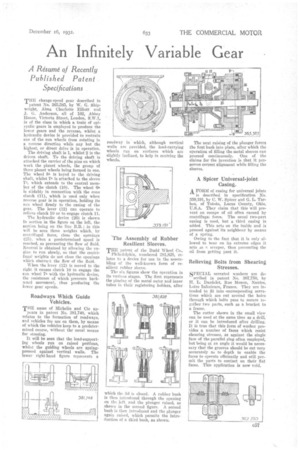
The Assembly of Rubber Resilient Sleeves.
THE patent of the Budd Wheel Co.,
Philadelphia, numbered 381,828, relates to a device for use in the assembling of the well-known form of resilient rubber sleeve.
The six figures show the operation in its various stages. The first represents the placing of the metal outer and inner tubes in their registering holders, after which the lid is closed. A rubber bush is then introduced through the opening on the left, and the plunger raised, as shown in the second figure. A second hush is then introduced and the plunger again raised, which permits the introduction of a third bush, as shown. The next raising of the plunger forces the first bush into place, after which the operation of filling the metal sleeves can proceed continuously. One of the claims for the invention is that it preserves correct alignment while filling the sleeves.
A Spicer Universal-joint Casing. A FORM of casing for universal joints
is described in specification No. 359,191, by C. W. Spicer and G. L. Tarbox, of Toledo, Lucas County, Ohio, U.S.A. They claim that this will prevent an escape of oil often caused by centrifug-ai force. The usual two-part casing is used, but a third easing is added. This acts on the inside and is pressed against its neighbour by means of a spring.
Owing to the fact that it is only allowed to bear on its extreme edges it acts as P. scraper, thus preventing the oil from getting past it.
Relieving Bolts from Shearing Stresses.
SPECIAL serrated washers are de scribed in patent No. 367,750, by H. L. Dardelet, Rue Menon, Nantes, Loire Inferieure, France. They are intended to fit into -corresponding serrations whicli are cut around the holes through which bolts pass to secure topther two parts, such as a bracket to a frame.
The cutter shown in the small view can be used at the same time as a drill, or it can be introduced after drilling. It is true that this form of washer provides a number of faces which resist shearing stresses, as against the single face of the parallel ring often employed, but being at an angle it would be necessary that the grooves should be cut very accurately as to depth to enable the faces to operate efficiently and still permit the parts to contact on their flat faces. This application is now void.