


A COMBINED SERVO AND MECHANICAL BRAKE,
Page 30
If you've noticed an error in this article please click here to report it so we can fix it.
A Resume of Recently Published Patent Specifications.
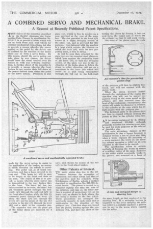
THE object of the invention described by the Societe Anonyme des Automobiles Unic, Prance, in specification No. 222,817, is to provide a brake which will act on both front and rear wheels by ordinary mechanical connections, but also to provide a means whereby the power applied to the pedal by the driver can be assisted by the reaction of the brake shoes and so form a servo brake. By this means, should the servo action not take place by any chance, the driver would have the usual control over his • brakes as with any ordinary construction. A further object of the invention is to provide a means whereby the front brakes do not receive their full share of the power derived from either the pedal or the servo action. Provision is also made for the servo action to assist in the application of the brakes, no matter in which direction the vehicle is travelling. The pedal (a)_is of usual construction, and has a beam pivoted to its rear end. This beam (e) will be seen to be longer at the front end than at the rear. The object of this is to provide a means whereby more power can be transmitted to the rear brakes than to the front. The beam (e) has two links attached to its ends ; the front link (f) transmits power through the bellcrank (g1) through the pull rod (g3) to the front-wheel brakes, while the link (i) transmits power through the lever (j) along the shaft (j1) and through the levers (j2) and by means of the pin (k) working in the slot (j3) through the lever (kl) and a shaft to the expander cam.
The expander cam and the pivot pia of the brake shoes are Mounted on a M6
plate (p), which is free to revolve on a nose provided at the rear of the gears box. The slot provided in the lever (j2) allows of a slight swinging motion of the plate (P) and is provided for this purpose. Cast integral with the gearbox is a boss which carries the fulcrum on which the lever (53), with its two projecting arms, is free to swing. It will be seen that, attached to the plate (p) are two rounded steel plungers, which bear against the projecting arms of the lever (s3), so that any swinging motion of the plate (p) dile to the inclination of the brake shoes to follow the drum, in either direction, will set up a movement in the lever (s3) which will result in a pull being transmitted through the rod (a) to the bell-crank (g1), and thence by means of the rod (g3) to the front-wheel brakes.
Other Patents of Interest.
TO avoid piston slap due to the dif
ference between the expansion of aluminium and other alloys and that of the cast-iron used for cylinders, Willy Kiichemann, of Berlin, adopts a method described in specification No. 211,878 detailed herein. The piston is turned to a diameter slightly less than the bore of the cylinder, and has on its inner surface a number of projections (C) at its lower end, as shown in both views, the left being a section on the line (AA). These projections are arranged diametrically opposite to each other and at right-angles to the direction of the gudgeon pin. Cast-iron rings are forced into the piston, bearing against the projections (C), and have the effect of die
totting the piston by forcing it into an oval form, the major axis of which fits the cylinder so that it will work freely. The sides of the piston near the ends of the gudgeon will then be slightly flattened, and wilt not contact with the piston walls.
When the piston becomes heated through the explosions of the engine the cast-iron ring will not be unduly expanded, being of the same metal as the cylinder, and also removed from the heat of the explosions; consequently, the piston will retain its diameter in relation to the cylinder at the axis, which lies at right-angles with the gndgeon pin.
The flattened parts of the piston skirt are free to expand without causing the piston to bind in the cylinder when hot.
AN invention registered by R. Bishop and numbered 223,968, although primarily intended for steering gear, may be used for such purposes as the control of throttles, etc. The main advantage claimed in the specification is that a longer leverage is obtained within a box of given size than when a worm engages the periphery of a worm segment, the worm on the steering column engaging a roller on an arm attached to the lever to be moved.
The specification refers to certain methods of forming the worm by means of a milling cutter of the same diameter as the roller which eventually works in. the groove, and mounted on a lever of
the same length as that employed in the steering box. If a swinging motion is imparted to the lever carrying the milling cutter in a suitable machine, a groove can be cut in the worm which exactly fits the roller. .