


HINTS ON MAINTENANCE.
Page 28
If you've noticed an error in this article please click here to report it so we can fix it.
How to Get the Best Out of a Vehicle, to Secure Reliability and to Avoid Trouble.
583.—The Care oi the Foden Water Pump.
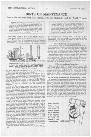
The water pump on the Foden steam wagon is a most efficient piece of mechanism if it be properly looked after. It is common knowledge amongst drivers that the pump seatings will require grinding in, and, perhaps, recutting, after several thousand miles have been covered by the vehicle. Recutting the seats need not be a difficult job if proper tools be employed, and reference to our drawing will show those necessary. They consist of a steel cap (A) screwed the same thread as the pump, and drilled through the centre to take a cutter spindle (B), the last-named having at its lower end a righthand thread and a shoulder so that a hardened cutter (C) can be screwed tight up against the shoulder.
To recut the seatings, screw the cutter on to the spindle with the 45 degree face downwards, push the spindle through the cap, and screw the cap into the pump until the face of the cap reaches the shoulder of the spindle. Add additional pressure by the use of spanner, and turn the cutter by means of a tap wrench on the squared portion of the shank. Do not make cuts which are too heavy, otherwise chattering may occur, but if the cleaning out be not sufficient at the first aitempt, repeat the process. After seatings have been recut and ground a few times, it will be noted that the cutter may sink below the level of the surrounding metal, and thus form a hollow which will prevent the valve having an effective opening. The problem is to reduce the level of the surrounding metal by reversing the cutter so that the teeth on the flat face can be employed. but this in itself is not sufficient, as a big cutter cannot be employed, and a neat way of overcoming the difficulty is to utilize a special spindle, the screwed portion for the cutter being turned eccentric. This enables a larger area to be cleared, and has proved most effective.
The correct lift for the suction, or bottom, valve is 1-16-in., and for the delivery, or top, valve 1-32-in. Consequently, the set-screws provided for adjusting purposes must be altered as the valves sink through the cutting and grinding of the faces
The cap, spindle and cutter can be borrowed from 844 the manufacturers, Fodens, Ltd. of Sandbach, but the special eccentric spindle is an invention of our contributor, and must be made by the driver or mechanic who does the repair..
584.—Reducing Oil Consumption.
In a certain lorry of Thornycroft manufacture the oil consumption steadily increased until it became an important factor in the running costs. Several attempts were made to cure the fault, but without success, until at last the following method was tried and met with a considerable measure of success.
Each piston is provided with three rings and each ring was pinned into position so that the gaps were well separated. The lower edge of the groove for each of the bottom rings was chamfered off slightly and small holes drilled into the interior of each piston through the chamfered portion.
585.—An Albion Correction.
With regard to Hint No. 582, published last week, the Albion Motor Car Co., Ltd., inform us that the correct method of adjusting gear meshing, in the 30-cwt. and 50-cwt. chassis, is to remove the inside wiper on the actuating shaft and lengthen it by about in. The respective part numbers are '21382 and 10784. In later chassis this wiper is adjustable.
586.—Curing Slackness in Splined Drop Arms.
A. considerable amount of backlash in the steering sometimes occurs through slackness in the connection between the drop arm and the wheel or sector crossshaft. In several well-known makes this connection takes the form of a splined coupling, and the top of the drop arm is often split to allow it to be tightened on to the cross-shaft by means of a bolt and nut. However, after considerable use, it is often found that the split cannot be closed sufficiently to keep the arm tight on the splines, in which case a saw-cut from i-in. to 1i-ins. deep, according to the size of the drop arm, made through the lowest keyway of the splines, will facilitate the tightening.