The Empire Commercial Chassis.
Page 8

Page 9

Page 10

If you've noticed an error in this article please click here to report it so we can fix it.
A New Subsidy-type Model. Capacity 41 Tons Gross. Some Ingenious Features.
Not the least of the many difficulties which confronted the British maker of new chassis during the early days of the war was the lack of facilities for obtaining materials. Prior to the outbreak of hostilities there was, to our knowledge, a large number of companies which had in hand designs for heavy commercial vehicles. It is owing to the difficulty stated that so few, comparatively, have, to date, been able to bring their plans to fruition.
The impressment of civilianowned lorries during the closing
months of 1914 and the acquisition by the Government of a monopoly of the output of practically all established lorry makers made the need for new chassis a pressing one. -Unfortunately the same causes tended to divert all engineering materials into the bands of firms working under Government contracts or making munitions.
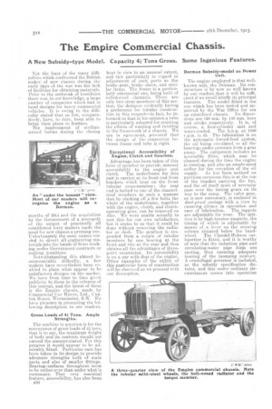
Notwithstanding this almost insurmountable difficulty, a few makers have nevertheless been enabled to place what appear to be satisfactory designs on the market. We have from time to time given publicity to these in the columns of this journal, and the latest of them is the Empire chassis, made by Commercial Car Hirers, Ltd., Caxton House, Westminster, S.W. We have pleasure in presenting the following description to our readers.
Gross Loads of 43 Tons. Ample Strengihs.
The machine in question is for the conveyance of gross loads of tons, that is to say, the maximum weight of body and its contents should not exceed the amount.stated. For this purpose it would appear to be admirably fitted. Particular care has been taken in its design to provide adequate strengths both of main parts and also of smaller fittings. Bearing ¼ surfaces throughout seem to be rather over than under what is customary. That very essential feature, accessibility, has also been B30
kept in view to an unusual extent, and this particularly in regard to adjustment of such parts as the brake gear, brake shoes, and similar items. The frame is a particularly substantial one, being built of rolled-steel channels. There are only two crosg members'of this section, the designer evidently having a. preference for tubular construction in this respect—in fact, he in formed us that in his opinion a tube is particularly adapted, for resisting the effects of warping and twisting in the framework of a chassis. We are in agreement, provided that the design of the connection between frame and tube is right.
Exceptional Accessibility of Engine, Clutch and Gearbox.
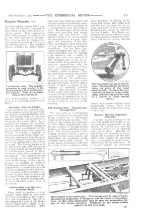
Advantage has been taken of this form of member to provide unusual accessibility to the engine and clutch. The underframe for this unit is carried_ at its front end from brackets which bear on the front tubular cross-member ; the rear end is bolted to one of the channelsteel members in such a manner that by slacking off a few bolts the whole of the underframe, together
• with the engine, clutch, and clutchoperating. gear, can be removed en bloc. IN e were unable actually to test this for our own satisfaction, but it seems to us that it could be done without removing the radi&tor or dash. The gearbox is suspended from a couple of tubular members by one bearing at the front and two at the rear and thus obtains all the advantages of threepoint suspension. Its accessibility is on a par with that of the engine. Other examples of the utility of this particular form of construction will be observed as we proceed with our description.
Dorman Subsidy-model as Power Unit.
The engine employed is that wellknown unit, the Dorman. Its construction is by now so well known by our readers that it will be sufficient if we recall briefly its principal features. The model fitted is the one which has been tested and approved by the War Office for use
en subsidized chassis. Its dimensions are 120 mm. by 140 ram. bore and. atroke respectively. It is, of course, a four-cylinder unit and water-cooled. The b.h.p. at 1000 r.p.m. is 45. The lubrication is on the automatic forced-feed system, the oil being circulated to all the bearings under pressure from a gem. pump. The equipment includes an accessible filter, which may be cleaned during the time the engine is running, and also an ample-sized orifice for the reception of the oil supply. As has been noticed on previous occasions this is at the top of the bracket carrying the fan, and the oil itself must of necessity pass over the timing gears -on its way to the sump. The valve gear, as is now customary, is enclosed in dust-proof . casings with a view to ensuring silence in operation and ease of lubrication. The tappets are adjustable for wear. The ignition is by high-tension magneto, the timing of which is adjustable by means of a lever on the steering column situated below the handwheel. The Claude]-Hobson carburetter is fitted, and it is worthy of note that the induction pipe and circulating-water pipe form one casting, thus ensuring adequate heating of the incoming mixture. A centrifugal governor is included, as the subsidy specification dictates, and this under ordinary circumstances comes into operation Empire Chassis con, when the engine reaches 1000 r.p.m. but may be altered if desired to take effect at any other predetermined speed. This component takes effect as part of dual control on the main carburetter throttle. The driver is able to regulate the fuel supply by means of a lever on the steering column. The standard chassis includes an engine 'fitted
with thermo-syphon cooling. If desired, a centrifugal pump can be added.
Radiator. Friction Clutch.
The cooling of the water is effected by means of an up-to-date builtup radiator, this being fitted up with top and bottom boxes of east alit, minium, and the central portion is composed of vertical tubes: As is apparent by reference to the illustrations, this component is designed so as to add considerably to the general appearance of the complete vehicle. It is built to conform to the requirements otWar Office specification and carried from the main frame in trunnion brackets, anchorage to the dashboard is effected by a tie rod. The friction clutch is of the lined cone type with the spring so arranged that the thrust from it is self-containe‹.1 except on those occasions when this component is disengaged. The clutch-operating gear is one of the interesting features of the design of this chassis. Instead of utilizing • an ordinary ball-bearing thrust washer for dis-' engagement, a substantial journal bearing is utilized for this function. It is possible by this method to eliminate the play which is frequently developed when the designer adheres to the former arrangement. A very effective . clutch stop is
embodied. • .
Clutch-shaft and Gearbox. Propeller Shaft.
From clutch to gearbox a short straight shaft fitted at both ends with universal joints of the leatherdisc type is employed. One of the advantages of a joint of this kind is that it lends itself readily to dismantlement. and assembly. After
removal of this shaft the clutch and the gear become immediately accessible so that the whole arrangement is commendable from this point of view. The gearbox is of the silentchain type providing four speeds forward, and one reverse. The change of gear is effected by means of a. swinging lever in a gate. Here again the necessities of the War Office specification have been kept in view and the gate is arranged accordingly. As we have previously remarked this unit is threepoint suspended from the tubular cross members, and it might be added that after the removal of three hearing caps it can be removed entire. From gearbox to the overtype worm-driven axle the power is transmitted by a tubular shaft with "sta-rpiece and two-jaw" couplings similar in design. They are completely enclosed by metallic covers and ample facilities are provided for the satisfactory lubrication of the bearings, which are unusually-large ; further, ingress of dirt or water or 'escape of the lubricant is carefully guarded against The alteration in length of this -shaft which takes Wace on the road owing to deflection of the road springs is arranged for by allowing the splined end of the shaft to move freely in the boss of the coupling.
Full-floating Axle. Forged Loadbearing Part.
The rear axle is a full-floating one, the whole of the imposed load being carried by a substantial forged double-banjo member. The ends of this forging are machined to War Office specification sizes for the reception of floating bronze bushes on these mild-steel wheels be.a,r. The circular portion of this forging, of course, serves in part as a casing for the worm, wheel, and differential, the remainder of the covering being steel castings. It seems almost 'needless to add that the whole of the mechanism of this axle, including the driving shafts, worm and wheel, differential gear and the ball bearings can be entirely. removed without otherwise disturbing the chassis or need for the use of jacks. Both brakes are mounted on the rear wheels, separate drums being provided for ernerT gency and service brakes. By this
means the excessive heating which occasionally occurs when both brakes are fitted on the •same drum, is obviated.
Brakes. Several Ingenious • • Features.
A glance at our drawing of the axle will enable the reader to understand the arrangement of the brakes. It will be seen that the operating shafts are on opposite sides of the drum. That for the foot brake, for example, is shown, and it will be noted that the same shaft which carries the operating cam is prolonged so as to form a fulcrum pin for the side brake. In a similar manner the side-brake
Empire Chassis—con.
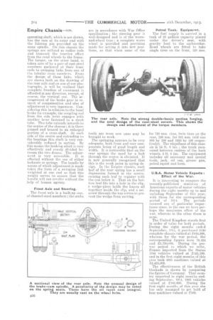
operating shaft, which is not shown, has the cam at its outer end with the fulcrum pin provided on the same spindle. On this chassis the springs are utilized as radius rods and transmit the tractive effort from the road wheels to the frame. The torque, on the other hand, is taken care of by a pair of cast-steel members anchored at their front ends to swinging links from one of the tubular cross members. From the design of these links, which are shown both on the drawing of the rear axle and on one of our photographs, it will be realized that complete freedom of movement is afforded in any direction, except, of course, the vertical one. The ar • rangement of the brake gear in respect of compensation and also of adjustment is very ingenious. Considering this in relation to the hand brake for example, the coupling rod from the side lever engages with another lever fastened to a short tube. This tube extends inwards to the centre of the chassis ; it is there pinned and brazed to an enlarged portion of a cross-shaft. At each side of the centre and extending to the bearings this shaft is very considerably reduced in section. By this means the braking effort is very effectively and evenly divided between the two drums. The adjustment is very accessible. it is effected without the use of either locknuts or springs. The handle by means of which adjustment is made lakes the form of a swinging link weighted at one and so that this weight serves to ensure that the handle will not revolve without the help of human agency.
Front Axle and Steering.
The front axle is it built-up one, of channel-steel members ; the stubs are in accordance with War Office -specification ; the steering gear is well-designed and is of the wormand-wheel type ; a complete worm wheel is provided and provision made for setting it into new positions, so that when some of the teeth are worn new ones may be brought to work.
The springing appears to be very adequate, both front and rear components being of good length and width. It is noticeable that on the rear springs the need for a bolt through the centre is obviated. It is now generally recognized that this is the weak point in spring design. In the Empire chassis, each leaf of the rear spring has a small depression formed in the centre, causing each leaf to register with the one below it. That on the bottom leaf fits into a hole in the clip, a wedge-piece holds the leaves all together in-side the clip, and a setscrew through the top serves to prevent the wedge from moving. Petrol Tank. Equipmt>int.
The fuel supply is carried in a tank of 25 gallons capacity placed under the driver's seat,, with gravity feed to the carburetter. Road wheels are fitted to take single tires on the front, 120 mm.
for 720 mm. rims, twin tires on the rear, 120 mm. for S81 mm. (old size 900 by 120 and 1050 by 120 respectively). The wheelbase of this chassis is 14 ft. 6 ins. ; the track rneasured between centres of the back wheels, 5 ft. S ins. The equipment includes all necessary and special tools, jack, oil can, grease gun, petrol squirt and horn.
U.S.A. Motor Vehicle Exports : Effect of the War.
It is interesting to compare the recently-published statistics of American exports of motor vehicles during the eight months up to and including September of this year, with those for the corresponding period of 1914. The periods covered are of particular importance since, in the one we have perhaps the maximum effect of the war, whereas in the other there is none.
The United Kingdom stands first in order of value for both periods. During the eight months ended September, 1914, it purchased 5130 complete chassis valued at £856,200, whereas for the war period, the corresponding figures were 19.434 and £5,730,000. During the rewar period to which we refer, France imported from the States 1044 vehicles valued at £125,100, and in the first eight months of this year took 4885 machines valued at £2.425,000.
The •effectiveness of the British blockade is shown by comparing the figures of Germany. That country imported in eight months ending September. 1914, 1003 vehicles valued at £160,000. During the first eight months of this year she has only managed to get hold of four machines valued at £560.


