Patents Completed.
Page 20

If you've noticed an error in this article please click here to report it so we can fix it.
Making Dunlop Tires. Vandervell Electric Starter Switch. Locking the Differential. Combined Road and Rail Vehicle.
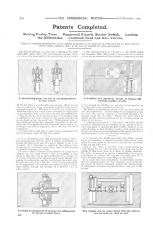
At the top there is an internally-grooved ring, which receives the cover when it is to be compressed, and the presser head is mounted beneath it. This head is carried on a trunk piston, which has within it a second piston connected to toggle joints on an expanding head which enters the ring above-mentioned.
When the tire has been inserted in place, low-pressure water is admitted to the large cylinder at the bottom and lifts the presser head up into the mould ring. High-pressure water is then admitted through the telescopic connection on the lefthand side of the space above the innermost piston, and by depressing it the head is expanded, and in this way the tire is compressed.
To release the tire the high-pressure water is discharged and the low-pressure water lifts the inner piston.
F. G. G. ARMSTRONG, No. 1793, dated 3rd February, 1915.— The accompanying drawing shows a simple arrangenient for locking the differential gear of a motor vehicle to put it out of action. It is illustrated as applied to the ordinary form of gear having two bevel wheels and a crown wheel carrying the pinions engaging with them. The crown wheel is formed on the outside of a casing which contains the two bevel wheels. Pins are mounted in this easing so that they can be pushed through it to engage one of a series of holes in the adjacent bevel wheel, thereby preventing its independent rotation and locking the whole, gear. The pins are moved by a flat disc, which is advanced axially by its engagement with suitable cam surfaces when it is partially turned through the medium of a Bowden wire or other control.
at the moment of switching on, and after it has speeded up it is changed over to a series arrangement. The battery is divided into two parts of, say, four cells and two cells respectively. The field magnets are connected across the four cells, and the armature. is connected through a resistance across the two cells. Finally, the field switch is opened and the armature and field are pat in series across the whole. of the battery.
A pedal-operated switch is illustrated; the pedal spindle carries the contracts for the armature circuit, and in its downward movement it operates the field switch, which is on an inclined guide, so that the field switch is first closed during the downward movement and released at the end of such down. ward movement to give the full series connection.
A. C. DUNHAM, No. 10,132, dated 12lli July, 1015.—Accordfag to this invention, a vehicle is provided with wheels which enable it to run either on the road or on rails, the conversion occupying but little time. Each of the wheels is provided with a tread having an inside flange, for use when running on the rails, and on the outside of this tread there is a feline of smaller diameter. This folios is arranged to receive a detachable rim carrying a pneumatic or cushion tire, but the tire itself must be of larger diameter than the inner flange on the wheel.
It is stated that this arrangement is particularly serviceablu fur carrying goods for long distances, as it gives the advantages of railway transport without the. disadvantages of independent collection and distribution at each end of the Journey.


