


The Reduction of Brake Fade
Page 60
If you've noticed an error in this article please click here to report it so we can fix it.
TO reduce brake fade by improving the cooling and sharing the work evenly between the shoes, is the aim of a modification shown in patent No. 778,57/ (Ford Motor Co., Ltd., 88 Regent Street, London, W.I.) The patent refers to self-energizing brakes in which a primary shoe provides additional working force to a secondary shoe.
Referring to the drawing, a primary shoe is shown at 1 and on the other side is the secondary shoe 2, both being located on a pin (3) at thc top. When the shoes are energized ,by the' eipander (4) the primary one transfers a force via the adjustable connector (5) to the secondary shoe, assuming counterclockwise rotation.
The essence of the patent is that the friction facing on the primary shoe is only two-thirds the width of the one on the main shoe. This has two advantages; it equalizes the rate of facing wear and provides a valuable cooling space at the sides of the narrower facing.
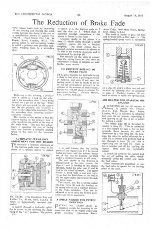
AUTOMATIC CLEARANCE ADJUSTMENT FOR DISC BRAKES 'TO maintain a constant clearance as I the friction pads wear away is the object of a scheme shown in patent No. 778,766. (The Goodyear Tire and Rubber Co.. Akron, Ohio, U.S.A.) It refers to hydraulically operated disc brakes.
A section through a hydraulic cylinder is shown in .the drawing, the parts being in the " on position. The piston A34 • is shown at 1, the friction pads at 2 and the disc at 3. When fluid is admitted tbroitgh connection 4 the piston is forced to the right.
Attached rigidly to the piston is a stem (5) which slides through a small auxiliary, piston (6) via a friction coupling. The small piston has a limited endwise movement (as shown at 7); this is the working clearance and is maintained by springs (8).
The friction on the stem is greater than the spring force so that once an adjustment is made it remains so until further wear occurs.
TO PREVENT BOILING OF BRAKE FLUID
ITis quite possible for hydraulic brake fluid to boil after a prolonged period of braking, and even if not near the boiling point, it can be made to do so by the sub-atmospheric pressure in the cylinder at the moment of brake release. Patent No. 778,429 shows a scheme for
preventing boiling, (Morris Motors, Ltd., Cowley, Oxford.) It is well known that the boiling point of any liquid rises if it be placed under pressure, and the scheme makes use of this fact by keeping the fluid under a residual pressure at all times.
The unit shown in the drawing is incorporated in the pipe system, the pipes (1 and 2) leading to the master cylinder, whilst the other pair (3 and 4) lead to the wheel cylinders. The upper circuit is fitted with a one-way valve (5) so that the fluid flows to the brakes via the upper pipes and returns through the lower ones.
This circuit, too, has a spring-loaded one-way valve (6) and the loading on its spring will set up a residual pressure in the brake cylinders. This can be adjusted so as to raise the boiling point above any likely maximum.
A SPRAY NOZZLE FOR PETROL INJECTION
PATENT No. 778,007 shows an injection nozzle for inserting in the induction pipe of an engine employing petrol injection. (American Bosch
Arma Corp., 3664 Main Street, Springfield, Mass., U.S.A.) The body is bored to pass the fuel and is fitted with a filter unit (1). The spring-loaded spray valve is assembled on a disc (2) which is then inserted and secured by spinning over or crimping at edge 3. Packing washers (4) are used as shims to adjust the spring load.
MR HEATER FOR STARTING OIL ENGINES
A STARTING aid for oil engines is 1—I shown in patent No. 778,241. (C.A.V., Ltd., Warple Way, Acton, London, W.3.) It operates by releasing fuel into the air stream, vaporizing it and igniting it;' all this is set in action by pulling a cabte.
The intake pipe (1) is threaded to receive a plug (2). This is connected to a fuel supply by pipe 3, but no fuel normally flows because its path is obstructed by a flat valve (4). If, however, the valve be pulled,sideways by a cable (5) it unseats and permits fuel to run through a bore (6) and into a vaporizing coil of wire (7). Next to this is another coil (8) for igniting the vapour. Both coils are electrically heated.
A switch (9) controls the current and the act of pulling the cable simultaneously closes the switch and opens. the fuel valve.
Other-variants are described; in one the fuel valve is opened by the heating effect of the coils.