


A NEW PRIMING GEAR.
Page 32
If you've noticed an error in this article please click here to report it so we can fix it.
A Résumé of Recently Published Patents.
The apparatus which is described in
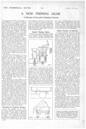
No. 165,596, by A. J. Adams, would be mainly useful, we imagine, in conjunc tion with a mechanical engine-starter, as it provides means whereby an engine may be primed by the driver without there being any necessity for him to get down from his seat. It consists, in the main, of a mixture pump arranged, in the particular illustration which we have selected for reproduction in conjunction
with the float chamber of carburetter.
Other constructions are described and illustrated in the specification itself. • The lid of the float chamber is perforated, and carries a skirt which depends downwards to such a depth that its lower edge is a short distance below the level of the petrol in the float chamber. This
skirt is a little less in diameter on the
outside than the interior of the float chamber, so that an annular chamber is left between the two. Mounted above the float chamber is a cylinder containing a plunger; the plunger is in communica, tion, by means of links and levers, with operating gear located conveniently near to the driver.
The top side of the plunger is in communication with the atmosphere; the underside with the space within the float chamber and with the induction mil-lift:11d of the engine. As regards the former connection, a ball valve is so arranged that it only allows the passage of petrol-laden air into the cylinder. This petrol-laden air is drawn from the float
chamber, the said air being compelled on its way to the pump cylinder to pass be
neath the skirt, which depends from the cover of the float chamber, and is induced into the pump cylinder on theupstroke of its plunger. On its downstroke the air, is slightly compressed, and passes by way of a special valve to the engine in duction manifold, near which it enters at points near the inlet valves of the engine cylinders.
It is necessary to refer briefly to the special valve which is located at the out let from the priming pump. This is illus trated as an inset to the drawing which we reproduce ; the valve is a combined piston and poppet ; the poppet head is beneath and takes its seating above the passage which leads to the engine induction manifold. The plunger above is somewhat larger_in diameter than the head of the poppet, while tbe upper side of the plunger is in communication with the atmosphere. When the petrol-laden air is delivered under slight compression to this valve, itlifts it because of the fact
that the plunger is of greater diameter. than the poppethead, thus allowing the priming mixture to pass to the engine.: By judicious proportioning of the diameter of this plunger and of the Poppet head, the correct pressure for the priming mixture may be attained.
Beading for Platform Bodies.
Patent No. 165,692, by S. Alley, describes a method of constructing a rail or beading for the edges of platform lorry bodies. The beading is made from sheet steel pressed out into an inverted
U shape. It is stiffened at intervals throughout its length by ferrules which are disposed transversely to the main • section and secured in place by rivets. B36 The heading is secured to the main portion of the body by vertical bolts, provision for which is made in theobeading as it is-stamped, the provision taking the form of countersunk holes, which are sufficiently deep, to ensure, that the round head of the bolt comes below the level of the beading proper.
Saurer Tipping Body.
The tip-lorry body construction, which forms the subject of No. 157,246, by Soc. A. A. Sourer, although described and illustrated in conjunction with that form of tipping gear which made the Sourer exhibit such an important feature of last year's commercial vehicle exhibition at Olympia, is nevertheless clearly applicable to most other forms of tip-gear. It relates to the arrangement whereby the side or 'end door of the lorry automatically swings open as the wagon is tipped. The Sourer deign, however, has this-important feature, for which novelty is claimed, that whereas in previous designs the swinging door has been hung from its upper edge, which is immovable, and which is therefore rather in the way -when the wagon is being filled, in this case the wagon side is hinged both at top and bottom. When tipping, the side automatically 'swings open from, and rests on, the top hinge. For filling, the whole side, including the top hinge, swings out of the way round the bottom edge.
Other Patents of Interest.
• A rather ingenious method of cooling the circulating water of an internal-combustion engine is described by R. M. Alexander in No. 165,556. The inventor shows a radiator on his drawings, but points out in the specification that this need' onlybe a dummy, provided in order to enable the appearance of the motorcar on which it is used to conform to conven tional ideas on the subject. He cools and circulates the water by blowing into it a draught of compressed air. The air may enter the pipe leading from the bottom of the radiator to the cylinder, or it may be delivered by way of a horizontal pipe lying along the bottom tank of the dummy radiator and emerging in an upward direction from a coil formed at each end of the pipe, blowing the water up a spiral way formed in two tanks, one at each side of the dummy radiator.
Specification No. 165,516, by J. Garlick, describes a mechanical method of.rotating an engine valve each tithe it falls upon its seat. The lower end of the valve tappet is flat. Its underside is spudded, and the cam is arranged so that it is eccentric to the tappet proper. Consequently, each time the cam revolves it turns the valve tappet, which movement is communicated to the valve, on the stem ef which a tongue is formed which fits into, a corresponding groove in the top of the tappet. In order that the action of the valve spring shall in no way interfere with the operation of this gear, the lower end of the spring is supported by a ball thrust hearing.
F. G. Bradbury describes, iiiNo. 165,343, one-method whereby the operating gear of a Ford car may be transferred from the left to the right side. • The existing pedals are broken, and new ones, with lateral extensions are welded on.
W. B. Pratt suggests that solid. tyres might conveniently be•built up of layers of duck or other material suitably impregnated with non-colloidal sulphurterpene compoand, the whole being sub• 'sequently encased in a covering of ordin ary solid rubber. The specification is numbered 165,662.
Specification No. 158,275 by Deutsche' Kraftpflug-Gesellschafte, refers to a previous specification, and describes a modi-, fication in construction. The subject is a motor plough, of the self-contained' type, and the inventor, by: concentrating all the gearing, control mechanism, etc., on the engine frame, thus relieving the plough frame; hopes to be able to reduce the overall weight of the machine.