


A Dual-ratio Hydraulic Brake
Page 48
If you've noticed an error in this article please click here to report it so we can fix it.
PATENT No. 595,520 discioses a hydraulic brake which provides a fast stroke -until resistance is encountered, after which it automatically applies a much higner pressure for the ictuat
braking. The patentee is S. Schnell, St. Louis, Missouri, U.S.A.
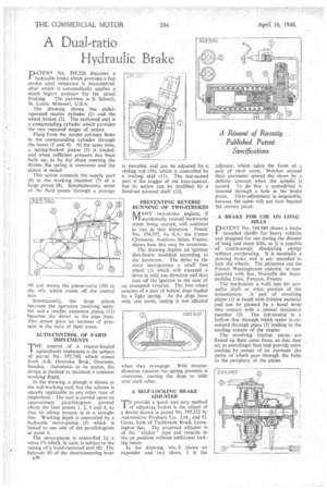
the drawing shows the pedaloperated master cylinder (1) and the wheel brakes (2). The sectioned unit is a compounding cylinder which provides the two required stages of action.
Fluid from the master cyLoder flows to the compounding cylinder through the bores (3 and 4). At the same time, a spring-backed piston (5) is loaded, and when sufficient pressure has been built up, as by the shoes meeting the drums, the spring is overcome and the piston is raised.
This action connects the supply port 16) to the working chamber (7) of a large. piston (8). Simultaneously, some of the fluid passes through a passage 19) and moves the piston-valve (10) to the left, which closes off the central borc.
Subsequently, the large piston becomes the operative receiving member and a smaller extension piston (11) becomes the driver to the pipe lines. This action gives an increase of pressure in the ratio of their areas.
AUTO-CONTROL OF FARM IMPLEMENTS
THE control of a tractor-hauled agricultural implement is the subject `of pat:-..nt No. 595,740, which comes from AB. Overums Bruk, Overums, Sweden. Automatic in its action, the device is claimed to maintain a constant' working depth.
In the drawing, a plough is shown as the soil-working tool, but the scheme is equally applicable to any other type of implement. The tool is carried upon an approximate parallelogram pivoted about the four points 1, 2, 3 and 4, so thai its lifting motion is in a straight lint. Working depth is controlled by a hydraulic servo-piston (5) .which is linked to one Side of the parallelogram at point 6.
• The servo-piston iscontrolled by a valve (7) which, in,turo, is subject to the setting of a bani:VoPerated cam (8). The fulcruni (9) of the interconnecting lever
a.38
is movable, and can be adjusted by a sliding rod (10), which is controlled by a trailing skid (11). The last-named part is the trigger of the auto-control, but its action can be modified by a hand-set screwed shaft (12).
PREVENTING REVERSE RUNNING OF TWO-STROKES it AANY two-stroke engines, if 1V1 accidentally rotated backwards when being started, will continue to run in that direction, Patent No. 594,392, by S.A.' des Usines Chausson, Asnieres, Seine, France, shows how this may be overcome.
• The drawing depicts an ignition distributor modified according to the invention. The drive to the rotor incorporates a small free • wheel (1) which will transmit a drive in only one direction and thus cuts off the ignition in the case -of an attempted reversal. The free wheel consists of a pair of helical dogs loaded by a light spring. As the dogs have only one tooth, timing is not affected
when they re-engage. With reversedirection rotation the spring pressure is overcome, causing the dogs to slide over each other.
A SELF-LOCKING BRAKE ADJUSTER
TO provide a quick and easy method of adjusting brakes is the object of a device shown in patent No. 595,322 by Automotive Products Co. Ltd., and G. Gates, both of Tachbrook Road, Leamington Spa The proposed adjuster is of the "clicker" type and remains in the set position without additional locking mean.
In the drawing, whs.h shows an expander and two shoes, 1 is the adjuster, which takes the form of a pair of stud' cams. Notches around their perimeter spread the shoes by a definite amount when the spindle is turned. To do this a screwdriver is inserted through a hole in the brake drum. Over-adjustment is impossible, because the cams will not turn beyond the correct poiot.
A BRAKE FOR USE ON LONG HILLS
pATE,NT No. 594.989 shows a brake intended chiefly for heavy vehicles and designed for use during the descent of long' and steep hills, as it is capable, of continuously dissipating energy without overheating. It is esentially a slowing brake and is not intended to lock the wheels. The paientees are the French Westinghouse concern, in conjuncticin with Soc. Nouvelle des Automobiles Unic, Puteaux, France.
The mechanism is built into the propeller shaft or other portion of the transthission. A pair of revolving plates (1) is faced with friction material and can , be pressed by a hand lever into contact with a. central stationary member (2). The last-named is a hollow disc through which -water is circulated through pipes (3) leading to the cooling system ofthe engine The revolving friction plates are finned on their outer faces, so that they' act as centrifugal fans and provide extra: cooling by means of an currents -the paths of which pass through the hubsl to the periphery of .the plates.