


What Causes Blow-by in Petrol Engines
Page 32
If you've noticed an error in this article please click here to report it so we can fix it.
IT has generally been assumed that gas leakage past the pistons, or blow-by as it is usually termed, was caused by the rings vibrating radially at a frequency associated with their natural frequency, the gases escaping between the rings and the cylinder wall. It is because of this supposition that the term "piston-ring flutter" has been applied to the phenomenon.
In a series of experiments carried out by Dr. P. de K. Dykes, M.A., Ph.D., A.M.1.Mech.E., in order to determine more definitely the real cause of blow-by, much interesting data resulted. In his paper, "Piston Ring Movement During Blow-by in High-speed Petrol Engines," which was read at the Institution of Mechanical Engineers on Tuesday, he gave details of his research efforts, which, so far, have been most encouraging. .
Although not claiming that the explanation is novel, the author said it would appear that excessive blow-by is caused by a steady radial ring collapse, which occurs during the last portion of the compression stroke and the first portion of the firing stroke, the blow-by at those stages passing between the ring and the cylinder wall.
This radial collapse occurs whenever the ring is pressed against the upper side of its groove, providedthat, at the same time, the pressure above the ring is appreciably greater than the pressure below it, the limiting value of this pressure difference depending on the ring characteristics. Dr. Dykes said that this radial collapse never occurred when the ring was pressed against the lower side of the groove, because then the natural stiffness of the ring was adequately assisted by the gas, force.
Forces Governing Ring Position
Whether the ring were on the upper or lower side of its groove depended chiefly, said the author, on the resultant Of two forces on the ring—one due to inertia and the other to the difference between the gas pressure above and below the ring. At low speeds, he said, the resultant of these two forces was always downwards during the compre.ssion and firing strokes, and thus the ring remained on the lower side of its groove.
Taking the case of a piston on which only one compression ring is fitted, Dr. Dykes said the sequence of events would appear to be as follows:—(1) The ring lifts axially during the second half of the compression stroke; (2) gas pressure behind the ring is relieved; (3) the ring collapses radially inwards; (4) heavy blow-by occurs between the ring and the cylinder wall; (5) the ring drops axially during the first half of the firing stroke; (6) gas pressure behind the ring is restored; (7) the ring returns radially to the cylinder wall; and (8) heavy blow-by ceases.
Dr. Dykes said that it appeared from his investigations that excessive blow-by should not occur at high enginespeeds when using a piston and ring design in which, even if the ring moved axially because of inertia forces, the gas pressure on an adequate portion of the back of the ring remained substantially at the same value as the pressure of the gas attempting to leak past it. The author then dealt with two special designs of piston ring which were evolved to meet this requirement, one being L-shaped and the other of channel section. Results with both were promising, he said. With either design of ring in a single-cylinder engine, blow-by was found to be very small at all speeds up to 6,000 r.p.m.; in fact, it was so small that it was found difficult accurately to measure it.
For the purpose of his investigations, Dr. Dykes used a single-cylindered air-cooled engine, and he gave some interesting details of the manner in which he bad obtained his valuable data. In order to obtain a record of axial ring movement, he employed the principle of the electrical resistance strain gauge, using copper-nickel wire of 0.0015-in diameter.
This wire was hooked over an insulated peg fitted to the back of the upper compression ring. When the ring moved axially, the wire loop was stretched, and a cathode-ray oscillograph was deflected with the change in rastance. Whilst that was the principle, the practical application to the piston of an engine turning over at a high rate was the subject of much experimental work.
The thin wire loop had a resistance of 70 ohms., and was fed with 30 milliamperes d.c. from a 12-volt battery through a 330-ohm, non-inductive resistor. Two cathode-ray oscillographs were used, one being observed visually and the other photographed by a eine camera, the film in which was fed at constant velocity.
Radial Ring Collapse
An entirely different piston set-up had to be arranged for detecting radial ring collapse, but again records were obtained with the oscillograph. It was shown that ring cojlapse occurred consistently at 24 degrees before top dead centre. Recovery was more variable, but an average value was 60 degrees after top dead centre.
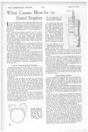
His research into the axial and radial movement of piston rings led Dr. Dykes to the surmise that a normal piston ring was unable to act as a seal against any appreciable gas pressure, unless its stiffness were assisted by gas pressure on its back surface. To check this belief he constructed a static test rig.
This test rig was designed to reproduce the conditions existing at the end of each compression stroke in an engine running at speeds associated with excessive blow-by. The piston ring was held stationary, so that it could be conveniently observed. Compressed air was used above the piston, and the first experiment was to measure the volume of blow-by as the air pressure was raised steadily to 40 lb. per sq. in. and then, subsequently, steadily reduced. Excessive blow-by started to occur at 26 lb. per sq. in. The ring gap was then checked, and it was found that it started to close noticeably when the air pressure reached 26 lb. per sq. in., and it continued to close as the pressure was raised. From 0.010 in., the normal gap, it closed to 0.002 in. at a pressure of 39 lb. per sq. in. A thin pitot tube was used to investigate the distribution of blow-by around the ring, and it was found that the first appreciable blow-by occurred at a point 60 degrees anti-clockwise from the gap at an air pressure of 20 lb. per sq. in. Clockwise from the gap no appreciable blow-by was observed until the air pressure was 26 lb. per sq. in„ the position being 35 degrees from the gap. At no time was there any appreciable blow-by in the area opposite to the ring gap,