 1
1 2
2 3
3 4
4 5
5 6
6 7
7 8
8 9
9 10
10 11
11 12
12 13
13 14
14 15
15 16
16 17
17 18
18 19
19 20
20 21
21 22
22 23
23 24
24 25
25 26
26 27
27 28
28 29
29 30
30 31
31 32
32 33
33 34
34 35
35 36
36 37
37 38
38 39
39 40
40 41
41 42
42 43
43 44
44 45
45 46
46 47
47 48
48 49
49 50
50 51
51 52
52 53
53 54
54 55
55 56
56 57
57 58
58 59
59 60
60 61
61 62
62 63
63 64
64 65
65 66
66 67
67 68
68 69
69 70
70 71
71 72
72 73
73 74
74 75
75 76
76 77
77 78
78 79
79 80
80 81
81 82
82 83
83 84
84 85
85 86
86 87
87 88
88 89
89 90
90 91
91 92
92 93
93 94
94 95
95 96
96 97
97 98
98 99
99 100
100 101
101 102
102 103
103 104
104 105
105 106
106 107
107 108
108 109
109 110
110 111
111 112
112 113
113 114
114 115
115 116
116 117
117 118
118 119
119 120
120 121
121 122
122 123
123 124
124 125
125 126
126 127
127 128
128 129
129 130
130 131
131 132
132 133
133 134
134 135
135 136
136 137
137 138
138 139
139 140
140 141
141 142
142 143
143 144
144 145
145 146
146 147
147 148
148 149
149 150
150 151
151 152
152 153
153 154
154 155
155 156
156 157
157 158
158 159
159 160
160 161
161 162
162 163
163 164
164 165
165 166
166 167
167 168
168 169
169 170
170 171
171 172
172 173
173 174
174 175
175 176
176 177
177 178
178 179
179 180
180 181
181 182
182 183
183 184
184 185
185 186
186 187
187 188
188 189
189 190
190 191
191 192
192 193
193 194
194 195
195 196
196 197
197 198
198 199
199 200
200 NEW SIX-WHEELERS for Passenger Work
Page 94
Page 95
If you've noticed an error in this article please click here to report it so we can fix it.
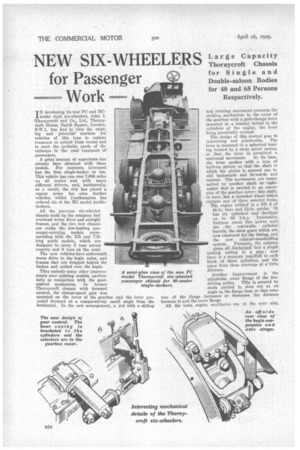
IN developing its new PC and 11Cmodel rigid six-wheelers, John I. Thornycroft and Co., Ltd., Thornycroft House, Smith Square, London, S'.W.1, has had in view the existing and potential markets for vehicles of this type to replace tramcars or extend tram routes and to meet the probable needs of the railways in the road transport of passengers.
A great amount of experience has already been obtained with these models. For instance, Liverpool has the first single-decker in use. This vehicle has run over 7,000 miles on all routes and with many different drivers, and, incidentally, as a result, the city has placed a repeat order for • nine further vehicles, whilst Eloutharapton has ordered six of the HO model doubledeckers.
All the previous six-wheeled chassis made by the company had overhead worm drive and straight frames, and the two new chassis are really the low-loading passenger-carrying models corresponding with the XB and Y_Blong goods models, which are designed to carry 5 tons across country and 6 tons on the road.
The new vehicles have underneath worm drive to the bogie axles, and frames that are dropped behind the dashes and arched over the bogie.
They embody many other improvements over existing models, particularly in connection with the gearcontrol mechanism. In former Thornycroft chassis with forward control, the change-speed gate was mounted on the cover of the gearbox and the lever projected forward at a comparatively small angle from the horizontal. In the new arrangement, a rod with a sliding
and rotating movement connects the striking mechanism in the cover of the gearbox with .a gate-change lever mounted in a bracket bolted' to the cylinders of the engine, the lever being practically vertical.
The design of this control gear ts interesting and practicable. The lever is mounted in a spherical bearing located by a stout spiral spring, so that the lever is permitted a universal movement. At its base, the lever meshes with a type of built-up pinion, so that the shaft to which the pinion is secured can be slid backwards and forwards and rotated. The movements are transmitted to another shaft at rightangles that is carried in an extension of the gearbox cover ; this shaft, in turn, has a sprocket wheel which engages any of three selector forks.. The engine utilized is a ZB 6 of 4i-in, bore and 5i-in. stroke. It has six cylinders and develops . up to 85 b.h.p. Interesting, features about this power unit . are . the renewable cyliuder barrels, the skew gears which are now employed for the timing,. and the new exhaust-manifoldiug
system. Formerly, the exhaust gases all discharged into a single casting ending in a pipe ; now there is a separate manifold to each block of three cylinders, and the pipes from these converge at a.little distance.
Another improvement is the adjustable outer flange of the fandriving pulley. This is secured by studs carried in slots cut at an angle in the flange boss, so that rotation of the flange increases or decreases the distance between it and the inner flange. All the main engine auxiliaries are at the near side, these including the carburetter. There is the usual line drive to the Simms dynamo and magneto; the latter has automatic advance. The carburetter is tilted on the engine to allow for the manner in which the engine is carried in the frame. Specialloid aluminium pistons are employed.
The circulation of the lubricant is effected by a sub' merged pump' driven by skew gearing from the camshaft. • Both main and big-end bearings are lubricated under pressure, and sprays of oil lubricate the cylinder walls.
The engine, dry-double-plate clutch and four-speed-andreverse gearbox are built up as a unit.
In the case of the FO model, the final-drive-gear ratio is 7.75-to 1. The gearbox ratios with the corresponding road speeds are as follow :—Fourth. direct (19i m.p.h.) • third, 1.56 to 1 (121 ; second, 2:75 to 1 (7 m.p.h.); first, 5.12 to 1 (3i ; reverse, 7.69 to 1 (21 m.p.h.).
The transmission to the bogie forward axle is by a twopiece propeller shaft with Spicer-type universal joints and a centre bearing carried in a Hardy flexible disc. A hollow shaft with two further all-enclosed joints connects the bogie axles. Both axle casings are of the forged, pot type.
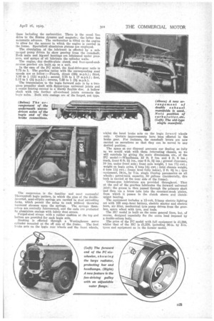
The suspension is the familiar and most successful Thornyeroft bogie 'pattern, in which the pins of the doubleinverted, semi-elliptic springs are carried in dual swivelling forks, which permit the axles to rock without throwing
torsional stresses upon the springs. The springs themselves are, centrally fulerummed, and the ends are protected by aluminium casings with fabric dust covers.
Forged-steel straps with a rubber cushion at the top and bottom are provided for each bogie axle.
Braking is effected through a Westinghouse servo cylinder mounted at the off side of the frame. The foot brake acts on the bogie rear wheels and the front wheels, whilst the hand brake acts on the bogie forward wheels
only. Certain improvements have been effected in the brake gear. For instance, the camshaft levers are now carried on serrations so that they can be moved to any desired position.
The space at our disposal prevents our dealing as fully as we would wish with these interesting chassis, so we will conclude by giving the main dimensions, etc.. of the FO model::—Wheelbases, 15' ft. 9 ins. and 4 ft. 6 ins.; track, front 6 ft. 31 ins., rear 6 ft. 31 ins.; ground clearance, 10 ins, under front axle ; front axle weight, 1 ton 171 ewt.; weight on bogie axles, 2 tons 141 cwt.; total chassis weight, 4 tons ni cwt.; frame level fully laden), 2 ft. 01 in.; tyro equipment, by 7-in. single Dunlop pneumatics on all wheels ; petrol-tank capacity, 50 gallons (incidentally, this tank is carried at the near side of the frame).
Grease-gun lubricators are provided throughout. That at the end of the gearbox lubricates the forward universal joint; the grease is then passed through the primary shaft and then via a brass tube into the constant-mesh pinion, from which it passes to the clutch sleeve and clutchspigot bearing.
The equipment includes a 12-volt, 5,1amp electric lighting set with 105 amp.-hour battery, electric starter and electric horn, air filter, mechanical tyre pump driven from the gearbox, spare wheel with tyre, and tools.
The HC model is built on the same general lines, but, of course, designed especially for the extra load imposed by a double-saloon body.
The price of the FO model with full equipment is £1,280, whilst that of the HC is £1,330, including 36-in. by 8-in. tyres and equipment as in the former model.