


Patents Completed.
Page 24
If you've noticed an error in this article please click here to report it so we can fix it.
An Improved Disc Clutch. A Novel Engine. Vaporizing Paraffin.
J. W. ROWLEY, No. 3706, dated 13th February, 1913. Cognate Application Nu. 854111913.—This specification describes a clutch of the type in which.% disc on one, member is gripped between two carrkd by the other member.
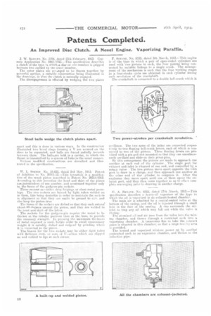
The outer plates are arr...i.nged to be 'drawn together by powerful springs, a suitable construction being illustrated in the drawings, so that. the clutch is normally engaged. The disengagement is effc-cted by wedging the two plates
apart and this is dune in various ways. in the construction illustrated two bevel rings forming a V are secured on the discs to be separated, and balls are forced radially inwards between them. The balls,are held in a carrier, to which the thrust is transmitted by a system of links in the usual manner.
Various modified constructions are described and illustrated in the specification.
W. L. SPENGT. No. 10,435, dated 3rd May, 1913. Patent of Addition to No. 20311i12.---This invention is a modification of the trunk piston described in Patent No. 2031111912. According to this invention the head and skirt of the piston aiie,independent.of one another. and arcinoined together only by the bases of the gudgeon-pin sockets. These SOCRO1S ar,, either drop-forgings or sheet-metal pressings. The two sockets are braced by light tubes welded on to them, this being desirable in order to maintain the sockets in alignment, so that they can easily be ground to size, and also keep the piston true The bases of the sockets are dished so that they each extencr abouLotlitegsees around the piston, and they are welded to the head ands-skirt of the latter.
The sockets for the gudgeon-pin require the metal to be thicker at the tubular portions than at the base, to provide the necessary strength. In pressing the maximum thickness of metal required is used, but;in order to avoid unnecessary weight it is suitably dished and redmed by grinding where it is connected to the piston.
The'braces for the two sockets may be either light tubes with flattened ends, or rods of 17-zecti0n which are slipped on and welded to lips at each corner.
P. ScuAnr, No. 5555, dated 5th March, 1913.—This engine is of the type in which a pair of open-ended cylinders are used with two pistons in each, the four pistons being connected by suitable linkage to a single crank. The arrangement of the mechanism is such that the four working stages in a four-stroke cycle are obtained in each cylinder during each revolution of the crankshaft.
The crankshaft is connected to a double bell-crank which it
oscillates. The two arms of the latter are connected respectively tctwo floating bell-crank levers, each of which is cullfleeted to two of the pistons. These floating levers are provided with a pin and slot mounted so that they can simultaneously oscillate and slide on their pivot-pins,
By this arrangement the pistons are made to approach one another at each end of the cylinder. The single port for exhaust and. inlet is situated at one end, and controlled by a rotary valve. The two pistons move apart opposite the inlet port to draw in a. charge, a»d then approach one another at the other end of the' cylinder to compress it After the explosion they move apart until one of them opens the exhaust port, and they then come together so as to effect corn plete scavenging prior to drawing in another charge.
A. BRYANT, No. 6528, dated 17th March, 1913.—This 3pecificAtion de.scribes a heavy-oil vaporizer of the type in which the oil is vaporized in an exhaust-heated chamber. The main air is admitted by a conical-seated valve at the bottom of the casing, and the oil is injected through a small hole in the face of the seating. A cup surrounds the airinlet to trap any oil which may fall out. while the valve is closing.
The atomized oil and air pees from the valve into the nixmg chamber, and thence through a restricted neck into a vaporizing chamber. A transverse flue to take the cosbauit gases is situated in this chamber, so that a large IIES'.11g area is provided.
The heated and vaporized mixture passes up by another contracted neck to an expansion chamber, and them.* to the induction pipe.