


A STEAM-WAGON PETROL CHASSIS.
Page 16
Page 17
Page 18
Page 19
If you've noticed an error in this article please click here to report it so we can fix it.
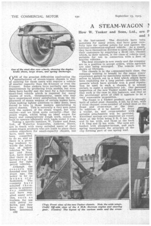
CINE of the greatest difficulties confronting the 1...1 manufacturer of steam-wagon chassis is that of catering for those users who require a vehicle of smaller capacity than the 8-tonner or even the 5-tonner. Some makers have partially met these requirements by producing 3-ton models, but even these have hardly met the need for a fast-running small-load vehicle which is required for many classes of work. Consequently, users who may have experienced every• satisfaction from the employment of steam wagons of certain makes have, when making lighter additions to their fleets, been forced to turn to those makers specializing in petrol chassis. This is naturally a very sore point with the makers of the steam wagon, but they realize—and we think quite correctly—that the steam wagon, whilst being an ideal wagon far heavy and comparatively rough work, cannot be built to operate efficiently with loads under 3 tons.
Although the concern was founded over 100 years aga, the policy is by no means oldfashioned. The company ha v e adapted t h e selves to presentd a y conditions, and have supplied many articles, such as trailers, for use with petrol vehicles, and they have for long been interested c32 in the last-named. The directors have been motorists for many years, and have gone carefully into the various points for and against the internal-combustion-engined vehicle. As a result, they have themselves decided to meet the wishes of their customers by supplying a 30-35 cwt. chassis which, in their opinion, is the class of vehicle most suitable for use in connection with a fleet of heavier vehicles.
The first example is now ready and the company are in a position to accept orders, while agencies are also being arranged. The vehicle will be shown at Olympia.
The chassis is in the Lomponent-built class, the company wishing to benefit by the many years' experience gained by specialists rather than themselves to launch out in a field which others have been exploiting for a long period—providing coinponents which have already won a good reputation be used in such a chassis, it is almost certain to make a satisfactory job. Our personal inspection of the new Tasker model has shown us that such is the case in this instance, and that at the provisional price of £395 it appears to be a very reasonable proposition.
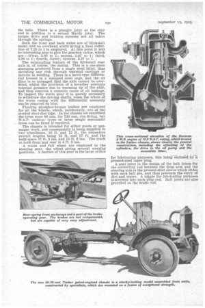
The frame is a Tasker product, and is strongly built of rolled steel channels, 4 ins. by 2 ins., with arstout channel cross-member of rolled steel at the front and cross-stays at the rear. In addition, if it be desired to draw a trailer, an end cross-member with suitable attachments will be provided. Excellent springs are employed all round, those at the front being 3 ft. 3 ins. long and 2f ins, wide, and those at the back 4 ft. long and 21 ins. wide. The eyes are bushed with phosphor-bronze, and each spring incorporates the principle of the clip forming part of one spring leaf. The power unit is a Dorman, type 4 M.R., having four cylinders of §0 mm. bore and 130 mm. stroke, cast in one with the upper half of the crankcase, a detachable head facilitating decarbonizing and valve grinding. The valves are at the near side, and the tappet gear is enclosed by two cast-aluminium covers, whilst at the off side of the water jacket are two rectangular pressed-steel covers, which facilitate the removal of sediment, etc. With au i R.A.C. rating of 15.9 the actual power developed is 19 b.h.p. at 1,000 r.p.m.
Carburation is attended to by a Zenith instrument bolted direct to the cylinders at the off sided whilst the four-bladed fan, with plates riveted to! a centre, is carried on an eccentric spindle, which provides adjustment for the link belt. The same belt is utilized to drive an impeller-type water pump, which is separate from the fan and is provided with a single large gland. Ignition is by high-tension magneto of B.T.H.' make with enclosed drive and mounted at the near side parallel with the crankcase. Behind it is a large bracket resembling an oil filler, but which, actually, contains the oil filter ; the cover is secured by wing-nuts, and cleansing of the filter is a matter of a few moments' work only, thus comparing very favourably with those engines in which access to the filter is only obtained either by removal of the sump or an awkwardly situated casing underneath it. The oil filler itself is of ample size, is situated on the off side, and is provided with a spring cap.
One of the features of this Dorman engine is that the cylinders are offset, thus reducing the side thrust on the cylinders during the power stroke.
The crankshaft, which is a high-tensile steel stamping, is carefully balanced and supported on three bearings, 2i ins. dia meter. Double-thrust ball bearings are utilized A dip stick is provided in the sump, which holds 1i gallons of oil, whilst the correct circulation of the oil is shown by a plunger indicator on the dash, beside which is the push-in-type switch.
Forced feed of the lubricant is employed for the main bearings and splash for the connecting rods and cylinders, any overflow being taken through a relief valve to the timing gear.
Provision is made for the fitting of a self-starter and a dynamo, and C.A.V. equipment will be employed where required.
The gearbox is built up as a unit with the clutch and engine. feature of the design, and one which has been strongly recommended by this jour nal, is that the clutch housing is open at the top. The unit is three-point suspended in the frame, at the front by a swivel bearing on a bracket secured to the front cross-member, and at the back by brackets bolted to the outsides of the frame side-members and passing under them.
A Ferodo-faced pressed-steel cone is employed for the clutch, which is external, with a single square-section spring having a self-contained thrust. The withdrawal gear con ststs of two direct acting radial ball races.
Four forward speeds are provided by the Dux gearbox, which is classified as No. 5. This is equipped with a lid carrying the extension bracket for the operating gear, so that this is relieved from all risk ofbinding through frame flexion.
Behind t h e gearbox comes a Hardy disc flexible joint built up of three plies and taking the drive to a tubular propeller shaft of large diameter with splined ends, which are brazed and riveted into the tube. There is a plunger joint at the rear end in addition to a second Hardy joint. The torque drive and braking stresses are all taken through the springs.
Both the front and back axles are of Kirkstall make, and an overhead worm giving a final reduction of 7.25 to l'is employed. At this point it will be interesting also to give the gearbox ratios, which are :--First, 3.85 to 1; second, 2.07 to 1; third, 1.38 to 1; fourth, direct ; reverse, 3.37 to 1.
The outstanding feature of the Kirkstall rear axle is, of course, the casing. This is a one-piece stamping produced from a single steel billet, thus obviating any risk through unsound castings or defects in welding. There is a bevel-type differential housed in a stamped steel cage, and the oil filler is so arranged that the axle cannot be overfilled, whilst the provision of a breather prevents internal pressure due to warming up of the axle, and thus removes a common cause of oil leakage. To inspect the worm gear it is merely necessary to withdraw the driving shafts, when the whole of the worm casing with the differential assembly can be removed en bloc.
Floating phosphor-bronze bushes are employed for all the wheels, which, incidentally, are of the riveted steel-disc type. In the chassis we examined the tyres were 80 mm. for 720 mm. rim fitting, but N.A.P. cushiontyres or large single pneumatic tyres can be fitted if required.
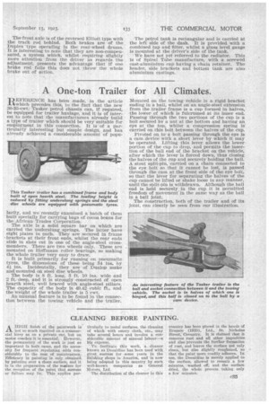
The chassis is intended for either goods or passenger work, and consequently is being supplied in two wheelbases, 10 ft. and 12 ft., the respective overall lengths being 15 ft. and 17 ft. and the body space 11 ft. 5 ins. and 13 ft. 5 ins. The track at both front and rear is 4 ft. 8 ins.
A worm and full wheel are employed in the steering gear, the wheel giving several wearing positions. A feature of this gear is the large orifice for lubricating purposes, this being enclosed by a pressed-steel taper plug.
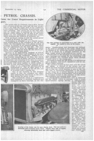
A neat point in the design of the ball joints for the connecting rod between the drop arm and the steering arm is the pressed-steel sleeve which slides with each ball pin, and thus prevents the entry of dirt and water. A nipple for lubricating purposes is screwed into each plug end. Ball joints are also provided on the brake rod. The front axle is of the reversed Elliott type with the track rod behind. Both brakes are of the Duplex 'type operating in the rear-wheel drums. It is interesting to note that they are non-compensated, a system which, whilst requiring slightly more attention from the driver as regards the adjustment, presents the advantage that if one brake rod• fails this does not throw the whole brake out of action. The petrol tank is rectangular and is carried at the left side of the dash. It is provided with a combined tap and filter, whilst a glass level gauge is mounted at the driver's side of the tank.
We have not yet referred to the radiator. This is of Spiral Tube manufacture, with a screwed cast-aluminium cup having a chain retainer. The header, side brackets and bottom tank are also aluminium castings.