


At the Engineering Exhibition.
Page 3
Page 4
Page 5
Page 6
If you've noticed an error in this article please click here to report it so we can fix it.
A New Mechanical Movement is Shown on the Lamplough Stand.
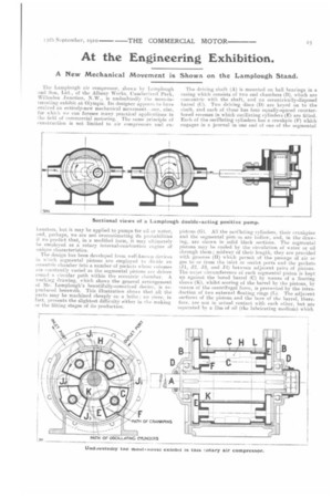
T-he Lamplough air compressor, shown by Lamplough and Son, Ltd., of the Albany Works, Cumberland Park, Willesden Junction, N.W., is undoubtedly the most-interesting exhibit at Olympia. Its .designer appears to have evolved an entirely-new mechanical movement—one, also, for which we can foresee many practical applications in the field of commercial motoring. The same principle of construction is not limited to air compressors and ex hausters, but it may be applied to pumps for oil or water, and, perhaps, we are not overestimating its probabilities if we predict that, in a modified form, it may ultimately be employed as a rotary internal-combustion engine of iinique characteristics.
The design has been developed from well-knot', ii devices in which segmental pistons are employed to divide an eccentric chamber into a number of pockets whose volumes are constantly varied as the segmental pistons arc driven round a circular path within the eccentric chamber. A working drawing, which shows the general arrangement of Mr. Lamplough's beautifully-conceived device, is reproduced herewith. This illustration shows that all the parts may be machined cheaply on a lathe; no piece, in fact, presents the slightest difficulty either in the making or the fitting stages of its production. The driving shaft (A) is mounted on ball bearings in a casing which consists of two end chambers (B), which are concentric with the shaft, and an eccentrically-disposed barrel (C). Two driving discs (D) are keyed on to the shaft, and each of these has four equally-spaced counterbored recesses in which oscillating cylinders (E) are fitted. Each of the oscillating cylinders has a crankpin (F) which engages in a journal in one end of one of the segmental
pistons P. All the osei!lating cylinders, their crankpins and the segmental pist4'.as are hollow, and, in the drawing, are shown in solid black sections. The segmental pistons may be cooled by the circulation of water or oil through them; midway of their length, they are provided with grooves (El) which permit of the passage of air or gas to or from the inlet or outlet ports and the pockets (J1, J. J3, and .T4) between adjacent pairs of pistons. The outer circumference of each segmental piston is kept up against the bored barrel (C) by means of a floating sleeve (K), whilst scoring of the barrel by the pistons, by reason of the centrifugal force, is prevented by the introduction of two external floating rings (L). The adjacent sorfaces of the pistons and the bore of the barrel, therefore, are not in actual contact with each other, but are separated by a film of oil (the lubricating medium) which
is relied upon to form a seal for the prevention, or the minimization of leakage from one pocket to another.
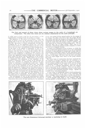
The operation of the device is as follows :—When the shalt is driven round in the direction of the arrow, it carries with it the two discs (D) and the oscillating cylinders (E); the power is thence transmitted, through the crankpins (F), to the segmental pistons (G), and these then travel round in a circle prescribed by the bore of the barrel and the outer circumference of the floating sleeve. As the path of the pistons is prescribed, so also is the path of the crankpins, but, as the latter path does not coincide with that of the centres of the cylinders (E), the cylinders are compelled to oscillate in their sockets; the effect of this oscillation is alternately to accelerate and retard the segmental pistons during their circular progress within the barrel, and the capacities of the pockets is thereby constantly varied. When used as an air pump or compressor, this alteration of the capacities of the pockets is employed : firstly, to draw in air through the inlet port; secondly to compress the indrawn air and, finally, to discharge it through the outlet port. Reference to the transverse section will show that : the pocket J4 is open for the admission of air; the pocket J3 contains an imprisoned charge of air at the same pressure as that at which it was admitted ; the pocket J2 contains a fully-compressed charge about to be delivered through the outlet port; and the pocket J1, having squeezed out one charge, is about to open again for the admission of air for a fresh cycle of operations. In this manner, there are four deliveries of compressed air per complete revolution. Two photographs of one of the demonstration models which are exhibited are reproduced herewith ; the first of these shows the pocket J1 just opening for the admission
of air—the pocket J4 has opened earlier for the escape of its charge; the other view shows that the pocket J2 has just closed, and that the charge in the pocket J3 has been compressed into about one half of its original volume. It should be noted that this pump's action is positive, and that there are no valves or reciprocating parts. We are informed that one of these pumps, when used as an exhauster, reduced the pressure inside a chamber to within one inch of a complete vacuum.
A model of an alternative form of blower, in which the charge is delivered against pressure but is not compressed internally, is also mounted on Lamplough's stand, and two photographs of the latter model are also reproduced herewith. A reference to these views—the third and fourth at the top of this page—will show that the inlet and outlet ports are both longer than those in the pump already described.
The latter form of construction has been employed for the purpose of forcing a charge into the cylinders of a two-cycle petrol engine, and such an engine is exhibited. Its two pistons operate on the same crank, and the charge is admitted through a port which is uncovered by the piston in No. 1 cylinder immediately after the exlaust port is uncovered by No. 2 piston. There are no valves, and the inrushing partly-compressed charge is relied upon to scavenge the previously-exploded charge. Speeds up to 3,000 r.p.m. have been obtained. A large range of Lainplough patent double-acting positive rotary pumps for oil or water is also exhibited, and three sectional views of this type of pump are given on this page. This pump comprises but three working parts: a. curved plunger path which is cast integral with the driving spindle; a curved plunger ; and a crankpin which engages in a bushed hole in the plunger and a slot in the plunger guide. The crankpin travels round the driving spindle at the same speed as the latter but is eccentric to it; it, therefore, imparts a, reciprocating motion to the plunger. Three views are given on page 25: the first shows the plunger in the middle position of its stroke; in the second one, the plunger is shown just about to start sucking in water at the top and delivering from the bottom of the plunger ; the remaining view is a longitudinal section through the complete pump.
One of these pumps is exhibited at the stand connected to a small cylinder into which it delivers oil against a pressure of 300 lb. per square inch.
Drummond Bros., of Guildford.
Mr. Arthur Drummond, the commander-in-chief of Drummond Bros., Ltd., of Ryde's Hill, Guildford, is nothing if not original in his ideas of machine touts. When his 31.; in.-centre screw-cutting lathe was first introduced, it was regarded as an innovation. Since that Lime, many new machines have been designed and produced in Drumrnond's works, and amongst them are: a 4 in. precision lathe; a 5 in. screw-cutting, surfacing, sliding and selfacting lathe; a 6 in. rising to 9 in. workman's lathe ; a low-priced bench shaping machine; a foot-driven radial drilling machine; a novel universal grinding machine ; the Drummond "five-pounder "—a. small and beautifullymade bench lathe, which is listed at £5; and a very-sturdy 9 in. manufacturer's lathe with an all-geared head. These tools embody ideas which are nothing short of revolutionary; yet they have all been justified by practical application in many workshops, and examples of them may be examined on the stand at Olympia.
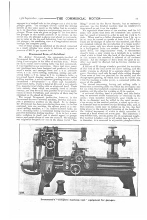
The newest Drummond production, however, is the Drummond-Barreto Universal machine, and this loot occupies a prominent position on the stand. In its design, Mr. Drummond has been more daring than ever, for he has combined, into one machine, the salient points of a universal milling machine, a 7 in. hollow-mandrel lathe, an 18 in. chucking lathe, a horizontal boring machine and a powerful horizontal drilling machine. It is, in fact, a complete workshop in itself, and it should appeal to garage owners and repair shops all over the country. The machine was originally designed for use on the steam yacht " Sea King," owned by the Baron Barreto, but so eminently practical was the finished machine that its constructors determined to put it on the market. We reproduce three views of the machine, and the full front view shows that both the headstock and tailstoek may be raised or lowered in order to suit the work to be done. When used as a lathe, diameters from in. up to 36 in. may be turned at speeds of from 5 to 270 r.p.m. There are 12 changes of speed for the mandrel, and these are obtained without the introduction of a large number of extra gears; only two wheels more than the usual four in a back-geared lathe are needed. Further, the lowspeed drive, for large-diameter work, is transmitted directly from a spur pinion on a layshaft to a toothed wheel which is fitted into the back of the faceplate, and in this manner the mandrel is relieved of all torsional stresses. All the changes of drive from one gear to another may easily be effected, but no friction clutches are employed.
A full set of 22 change wheels is provided, for variation of the feed of the lead screw for screw cutting, and the saddle traverse is effected by a separate shaft; the lead screw, therefore, need only be used while cutting threads. Three rates of feed are provided for the saddle, and the change-speed gearing, by which they may be varied even while the machine is under power; is contained within the apron of the saddle.
The slotted traversing, boring and milling table is fitted with a. swivelling slide rest which has two bases—one for use when the headstock centres are set at their lowest. position, and the other for working at 18 in. centres. A universal dividing head is provided, and this device may be mounted either horizontally or vertically on the saddle; when mounted horizontally, gear wheels up to 14 in. in diameter may be milled in the usual manner ; when swung to the vertical position, a wheel up to 40 in. in diameter may be mounted on the dividing head, and, in that position, teeth may be milled on its rim, the feed being given by the raising and lowering of the headstock, the vertical movement of which is easily controlled hv means of a hand wheel and worm gear. The headstock is very-solidly built, and its guides are of exceptional length. The mandrel is hollow, and it will admit bars up to 21 in. in diameter ; it is mounted in adjustable phosphor-bronze bearings. Every part of the machine has been designed so as to have ample surfaces for the wearing parts, and to hold up to the largest piece of work within its capacity. It is by no means a suitable machine for installation in a manufacturer's shops, but, for use in garages or where the work is both varied in kind and uncertain in quantity, the Drummond-Barreto machine may be made
of great practical service. Its price is about the same as a universal milling machine, and it will do all the work of such a machine with the added advantages that, when milling work gives out, the machinist need not be " sacked " or " stood off," but can withdraw the upper bar and milling attachments and use the machine, either as a lathe or a boring machine, for other work.