


A Variable-compression Engine
Page 68
If you've noticed an error in this article please click here to report it so we can fix it.
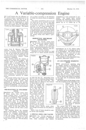
I T is well known that the efficiency of a petrol engine is proportional to its compression ratio, but this is at its optimum value only at full throttle. At lesser loads the compression is much lower, and it is to deal with this aspect that a new engine, shown in patent No. 713,992, has been designed. The patent comes from R. Skinner, 8162 East Jefferson Avenue, Detroit, Michigan, U.S.A. An unusual point in the patent is that all the claims are based on the use of a novel type of 'scaling-ring, the variable-compression feature being, apparently, incidental.
The drawing shows the scheme as applied to a sleeve-valve engine. The cylinder head (1) is slidable in the cylinder and is normally held in its upper position by a spring (2). The head can be moved downwards by feeding hydraulic fluid via port 3 into space 4. The actual movement is small, less than a in., but it would, of course, have a considerable effect on the compression ratio. The head may be controlled manually, or automatically by a servo mechanism sensitive to intake suction
The special sealing rings (5) are used for all sliding seals, and consist of frustro-conical flexible metal rings assembled in groups in the grooves. Without them, the patentee asserts, the corn pressi on-adjusting m e c h an i s m would be carboned up in half-an-hour's run.
PRE-SELECTION IN TWO-SPEED AXLES
PATENT No. 714,024 comes from Eaton Axles, Ltd., 25 Victoria Street, London, S.W.1. It discloses a means for making the gearshift in such an axle pre-selective. The actuating lever, instead of operating the gearshift direct, does so through the medium of a spring. If any substantial torque is being transmitted, the spring is merely stressed and no change takes place. Relief of the load allows the spring to operate and the ratio is then changed.
The drawing shows the essential details of the scheme. In the example shown, the changing mechanism is worked by an electric motor attached to the axle casing. The motor (1) has a screwed spindle extension (2) upon which works a nut (3). The nut moves A34 up or down according to the direction in which the electric motor is caused to run.
The actual gearshifting part is a rod (4) which has to be moved to the right or to the left as may be. A bellcrank
(5) pivoted at point 6 is the moving medium, its tail being trunnioned to the nut on the motor shaft. The sideways movement is transmitted through a double-helical spring (6) which flexes if the gearshift resists movement due to load. If the load be eased momentarily the spring would then effect a gearchange.
SIMPLIFYING DISC-BRAKE MECHANISM
PATENT No. 714,103, comes from H. Trevaskis and Dunlop Rubber Co., Ltd., 1 Albany Street, London, N.W.1. The subject is an improved form of operating mechanism for a disc brake. Robustness, efficiency and simplicity are the virtues claimed.
Attached to the axle casing is a rigid torque bar (1) which extends outwards to clear the disc (2). Depending from this is a pair of wishbone-shaped plates (3) one on each side of the disc. The friction pads are affixed to the bottom of these plates and the brake is brought into action by pulling the lower ends together so as to grip the disc. This may be performed by a hydraulic unit or other means acting on the swinging bolts (4).
The most novel feature of the scheme is that the plates are not hinged in any way to permit their gripping movement; they are attached to the torque bar by bolts (5) passing through rubber sleeves which allow just enough movement for the plates to work.
Such a type of brake should be easy to service and maintain.
712,473
A SPECIAL STEEL FOR VALVES
PATENT No. 713,162 describes a valve steel claimed to withstand heat, resist corrosion and remain
unattacked by lead compounds in particular. The patent gives several formula, the following being typical: chromium 12 to 30, nickel 2 to 35, manganese up to 17, cobalt up to 30, molybdenum up to 4.5, silicon under .25, sulphur up to .5, nitrogen up to .3, all in percentages. The carbon content is between 0.35 per cent and 1.5 per cent., whilst the remainder, of iron, should be at least 50 per cent.
The patentee is Alloy Research Corp., Baltimore, Maryland, U.S.A.
AN ALL-CERAMIC SPARKLNG PLUG E conventional sparking plug 'HE contains a multiplicity of parts which make the cost of production relatively high, especially when assembly is taken into account. A novel type of plug, claimed to be far less expensive to produce, is shown in patent No. 712,473. (United States Quarry Tile Co., Canton, Ohio, U.S.A.) As the whole plug could be moulded, a very high rate of production should be possible.
The chief feature of the design is that, with the exception of the electricity con ductors, the plug is made entirely of ceramic material, 92 per cent. of which is alumina. The drawing shows the main body which has a moulded thread (1) to receive the central electrode, whilst the bottom end is moulded to conform to the usual cylinder thread (2). To make an earth connection, this thread is sprayed with metal.
The central bore is a blind hole having at the bottom a thin septum of ceramic (3) between the electrode and the earthed shell. The application of a high voltage across this thin wall makes a microscopic puncture through which the spark can occur. No sealing arrangements, other than the long, close fit round the electrode, are considered to be necessary.