


A Limited-motion Differential Gear
Page 70
If you've noticed an error in this article please click here to report it so we can fix it.
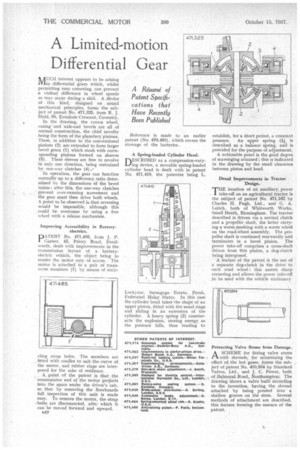
A Resume of Patent Specifications , that Have Recently Been Published
WAUGH interest appears to be arising IVIin differential gears which, whilst permitting easy cornering, can prevent a violent difference in wheel speeds as may occur during a skid. A device of this kind, designed on . sound mechanical principles, forms the subject of patent No. 471,825, from R, J. Ifield, 98, Evenlode Crescent, Coventry.
In the drawing, the crown wheel, casing ' and axle-end bevels are all of normal construction, the chief novelty
• being the form of the planetary pinions. These, in addition to the conventional pinions (2) are extended to form larger bevel gears (1) which mesh with corresponding pinions formed on sleeves (3). These sleeves are free to revolve in only one direction, being restrained by one-way clutches (4).--
In operation, the gear can function normally up to a difference.ratio deterMined by the dimensions of the bevel trains; after this, the one-way clutches ' prevent over-running movement and the gear must then drive both wheels. A point to be observed is that reversing would be impossible, although this could be overcome by using a free wheel with a release mechanism.
Improving Accessibility in Batteryelectrics.
PATENT No. 471,485, from J. P. Garner, 45, Priory Road, Kenilworth, deals with improvements in the transmission layout of a batteryelectric vehicle, the object being to render the motor easy of access. The motor is attached to a pair of transverse members (1) by means of encir
cling strap bolts. The members are frtted with cradles to suit the curve of the motor, and rubber rings are interposed for the sake of resilience.
, A point of the patent is that the commutator end of the motor projects into the space under the driver's cab, so that by removing the floorboards full inspection of this unit is made easy. To remove the motor, the strap -bolts are disconnected, afte: which it can be moved forward and upward.
u52 Reference is made to an earlier patent (No, 470,463), which covers the stowage of the batteries.
A Spring.loaded Cylinder Head.
DESCRIBED as a compression-varyling device, a movable spring-loaded cylinder head is dealt with in patent No. 471,410, the patentee being L.
Locky ear, Samagaga Estate, Perak, Federated Malay States. In this case the cylinder head takes the shape of an upper piston, fitted with the usual rings and sliding in an extension of the cylinder. A heavy spring (2) counteracts the explosion, storing energy as the pressure falls, thus tending to establish, for a Short period, a constant pressure. An upper spring (1) is described as a balance spring, and is provided for the purpose of adjustment.
A noticeable point is the good degree of scavenging attained ; this as indicated in the drawing by the small clearance between piston and head.
Detail Improvements in Tractor Design.
T'HE location of an auxiliary power take-off on an agricultural tractor is the subject of patent No. 471,162 by Charles H. Pugh, Ltd., and G. A. Leitch, both of Whitworth Works, Small Heath, Birmingham. The tractor described is driven via a normal clutch and a propeller shaft, the latter carrying a worm meshing with a worm wheel on the road-wheel assembly. The propeller shaft is continued rearwardly and terminates in a bevel pinion. The power take-off comprises a cross-shaft driven from this pinion, a dog-clutch being interposed.
A feature of the patent is the use of a separate dog-clutch in the drive to each road wheel ; this assists sharp cornering and allows the power take-off _to be used with the vehicle stationary Protecting Valve Stems from Damage.
AA SCHEME for fitting valve stems with shrouds, for minimizing the effect of the hot gases, forms the subject of patent No. 470,934 by Standard Valves, Ltd., and J. C. Power, both of Balmoral Road, Northampton: The drawing shows a valve built according to the invention, having, the shroud attached by being pressed into a shallow groove on the stem. Several methods of attachment are described, this feature forming the essence of the patent.